1. First steps in Reaktor Core - Native Instruments
1. First steps in Reaktor Core - Native Instruments
1. First steps in Reaktor Core - Native Instruments

Create successful ePaper yourself
Turn your PDF publications into a flip-book with our unique Google optimized e-Paper software.
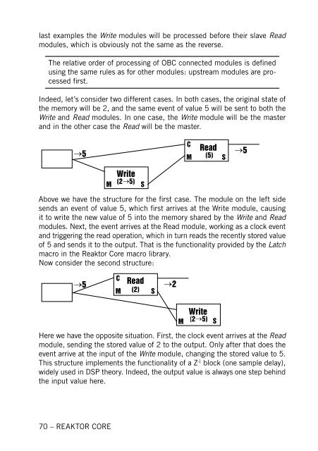
last examples the Write modules will be processed before their slave Read<br />
modules, which is obviously not the same as the reverse.<br />
The relative order of process<strong>in</strong>g of OBC connected modules is def<strong>in</strong>ed<br />
us<strong>in</strong>g the same rules as for other modules: upstream modules are processed<br />
first.<br />
Indeed, let’s consider two different cases. In both cases, the orig<strong>in</strong>al state of<br />
the memory will be 2, and the same event of value 5 will be sent to both the<br />
Write and Read modules. In one case, the Write module will be the master<br />
and <strong>in</strong> the other case the Read will be the master.<br />
�<br />
���<br />
70 – REAKTOR CORE<br />
������<br />
��<br />
������ ��<br />
��<br />
����� �� ��� � ��<br />
���<br />
Above we have the structure for the first case. The module on the left side<br />
sends an event of value 5, which first arrives at the Write module, caus<strong>in</strong>g<br />
it to write the new value of 5 <strong>in</strong>to the memory shared by the Write and Read<br />
modules. Next, the event arrives at the Read module, work<strong>in</strong>g as a clock event<br />
and trigger<strong>in</strong>g the read operation, which <strong>in</strong> turn reads the recently stored value<br />
of 5 and sends it to the output. That is the functionality provided by the Latch<br />
macro <strong>in</strong> the <strong>Reaktor</strong> <strong>Core</strong> macro library.<br />
Now consider the second structure:<br />
�<br />
���<br />
�� ����� �� ���� ��<br />
���<br />
������<br />
�� ������ ��<br />
Here we have the opposite situation. <strong>First</strong>, the clock event arrives at the Read<br />
module, send<strong>in</strong>g the stored value of 2 to the output. Only after that does the<br />
event arrive at the <strong>in</strong>put of the Write module, chang<strong>in</strong>g the stored value to 5.<br />
This structure implements the functionality of a Z -1 block (one sample delay),<br />
widely used <strong>in</strong> DSP theory. Indeed, the output value is always one step beh<strong>in</strong>d<br />
the <strong>in</strong>put value here.