1. First steps in Reaktor Core - Native Instruments
1. First steps in Reaktor Core - Native Instruments
1. First steps in Reaktor Core - Native Instruments

Create successful ePaper yourself
Turn your PDF publications into a flip-book with our unique Google optimized e-Paper software.
You don’t have any control over the place where automatic feedback resolution<br />
will occur. It occurs on an arbitrary signal wire <strong>in</strong> the feedback loop. It is not<br />
even guaranteed that the resolution will always occur on a particular wire—it<br />
could change <strong>in</strong> the next version of the software, it could change <strong>in</strong> response<br />
to a change elsewhere <strong>in</strong> the structure, and it could be different the next time<br />
you load the structure from disk.<br />
Hence, automatic feedback resolution is meant for the structures for which<br />
it’s not important where exactly the resolution occurs. For example, such<br />
structures might be built by users who are not deep enough <strong>in</strong>to DSP to understand<br />
these problems. Automatic feedback resolution allows them to still<br />
get reasonable results.<br />
If you need to have precise control over feedback resolution po<strong>in</strong>ts you<br />
can achieve that by explicitly <strong>in</strong>sert<strong>in</strong>g Z^-1 modules <strong>in</strong> your structures.<br />
These modules will formally explicitly elim<strong>in</strong>ate the feedback and automatic<br />
resolution will not be needed.<br />
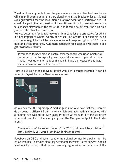
Here is a version of the above structure with a Z^-1 macro <strong>in</strong>serted (it can be<br />
found <strong>in</strong> Expert Macro > Memory submenu):<br />
As you can see, the big orange Z mark is gone now. Also note that the 1-sample<br />
delay po<strong>in</strong>t is different from the one which was automatically <strong>in</strong>serted (the<br />
automatic one was on the wire go<strong>in</strong>g from the Adder output to the Multiplier<br />
<strong>in</strong>put and now it’s on the wire go<strong>in</strong>g from the Multiplier output to the Adder<br />
<strong>in</strong>put).<br />
The mean<strong>in</strong>g of the second <strong>in</strong>put of the Z^-1 module will be expla<strong>in</strong>ed<br />
later. Typically you would just leave it disconnected.<br />
Feedback on OBC and other types of non-signal connections (which will be<br />
<strong>in</strong>troduced later) does not make any sense and, therefore, is not allowed. Should<br />
feedback loops occur that do not have any signal wires <strong>in</strong> them, one of the<br />
92 – REAKTOR CORE