1. First steps in Reaktor Core - Native Instruments
1. First steps in Reaktor Core - Native Instruments
1. First steps in Reaktor Core - Native Instruments
Create successful ePaper yourself
Turn your PDF publications into a flip-book with our unique Google optimized e-Paper software.
A typical situation <strong>in</strong> which denormal numbers appear for prolonged<br />
periods of time is <strong>in</strong> calculat<strong>in</strong>g exponentially decay<strong>in</strong>g values, as <strong>in</strong><br />
filters, some envelopes, and feedback structures. In such structures,<br />
after the <strong>in</strong>put signal reaches zero level, the output signal asymptotically<br />
decays to zero. Asymptotically means that the signal gets closer and<br />
closer to zero without ever reach<strong>in</strong>g it. In that situation, denormal numbers<br />
can appear and stay <strong>in</strong> the structure for relatively long time (until<br />
their absolute value falls below 10 -45 ), and that can cause a significant<br />
<strong>in</strong>crease <strong>in</strong> CPU load.<br />
Another situation <strong>in</strong> which denormal numbers may occur is when you<br />
change the precision of a float<strong>in</strong>g po<strong>in</strong>t value from a higher precision (64<br />
bit) to a lower precision (32 bit), because a value 10 -41 is not a denormal<br />
<strong>in</strong> a 64 bit precision float but it is a denormal <strong>in</strong> a 32 bit precision float<br />
(chang<strong>in</strong>g the precision of floats is discussed later).<br />
Let’s consider model<strong>in</strong>g an analog 1-pole lowpass filter with its cutoff set to<br />
20 Hz. Our digital signal values will correspond to analog voltages (measured<br />
<strong>in</strong> volts). Let’s imag<strong>in</strong>e that the <strong>in</strong>put signal level was equal to 1V (volt) over a<br />
long enough period of time. Then the voltage at the filter output is also equal<br />
to 1V. Now we abruptly change the <strong>in</strong>put voltage to zero. The output voltage<br />
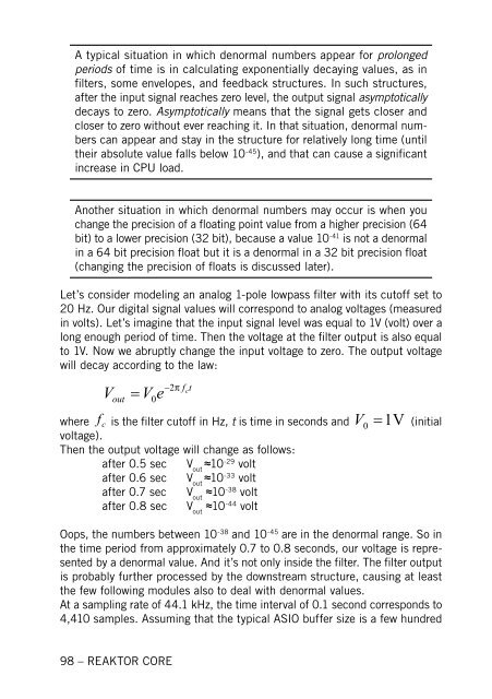
will decay accord<strong>in</strong>g to the law:<br />
V<br />
out<br />
� V e<br />
98 – REAKTOR CORE<br />
0<br />
�2�<br />
f t<br />
c<br />
where f c is the filter cutoff <strong>in</strong> Hz, t is time <strong>in</strong> seconds and 0 1V<br />
� V (<strong>in</strong>itial<br />
voltage).<br />
Then the output voltage will change as follows:<br />
after 0.5 sec V ≈10 out -29 volt<br />
after 0.6 sec V ≈10 out -33 volt<br />
after 0.7 sec V ≈10 out -38 volt<br />
after 0.8 sec V ≈10 out -44 volt<br />
Oops, the numbers between 10 -38 and 10 -45 are <strong>in</strong> the denormal range. So <strong>in</strong><br />
the time period from approximately 0.7 to 0.8 seconds, our voltage is represented<br />
by a denormal value. And it’s not only <strong>in</strong>side the filter. The filter output<br />
is probably further processed by the downstream structure, caus<strong>in</strong>g at least<br />
the few follow<strong>in</strong>g modules also to deal with denormal values.<br />
At a sampl<strong>in</strong>g rate of 44.1 kHz, the time <strong>in</strong>terval of 0.1 second corresponds to<br />
4,410 samples. Assum<strong>in</strong>g that the typical ASIO buffer size is a few hundred


