Tagungsband - BFT International
Tagungsband - BFT International
Tagungsband - BFT International
Sie wollen auch ein ePaper? Erhöhen Sie die Reichweite Ihrer Titel.
YUMPU macht aus Druck-PDFs automatisch weboptimierte ePaper, die Google liebt.
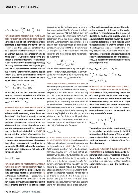
PANEL 10 // PROCEEDINGS<br />
0,18<br />
u / d < 4 : C = ––––– (0,1 ∙ ––– + 0,6)<br />
0 Rd,c<br />
γ d<br />
c<br />
PUNCHING SHEAR RESISTANCE OF FLAT SLABS<br />
WITH PUNCHING SHEAR REINFORCEMENT In<br />
Eurocode 2, the ratio of punching shear rein-<br />
forcement is determined only for the critical<br />
section u 1 and then used as a constant value<br />
for all sections until the verification is success-<br />
ful without punching shear reinforcement.<br />
Unlike DIN 1045-1, EC2 does not specify a gra-<br />
duation of shear reinforcement. The evaluation<br />
of test results showed that this approach sig-<br />
nificantly underestimated the required pun-<br />
ching shear reinforcement ratio for the first<br />
two sections. For this reason, the NAD applies<br />
a factor of 2.5 to the punching shear reinforce-<br />
ment in the first row and a factor of 1.4 to the<br />
reinforcement in the second row:<br />
(v – 0,75 ∙ v ) ∙ d ∙ u Ed Rd,c 1<br />
A = ––––––––––––––––––––––––––<br />
sw 1,5 ∙ (d/s ) ∙ f ∙ sinα<br />
r ywd,ef<br />
To account for the less effective embed-<br />
ment of stirrups in thin slabs, the effective<br />
design yield strength must be modified to<br />
f ywd,ef = 250 + 0.25 ∙ d ≤ f ywd .<br />
MAXIMUM PUNCHING SHEAR RESISTANCE OF<br />
FLAT SLABS In EC2, the maximum resistance<br />
is determined for section u 0 (circumference of<br />
the column) using the strut strength of beams.<br />
The analysis of punching shear tests at the<br />
maximum resistance level proves a strong cor-<br />
relation with the column circumference and<br />
concrete compressive strength, and sometimes<br />
leads to significant safety deficits [2] (FIG. 1).<br />
By contrast, the method of determining the<br />
maximum resistance of flat slabs as a multiple<br />
of the punching shear resistance without pun-<br />
ching shear reinforcement turned out to be<br />
appropriate. The NAD defines the maximum<br />
punching shear resistance of flat slabs with<br />
stirrups as follows:<br />
v Rd,max = 1,4 ∙ v Rd,c<br />
PUNCHING SHEAR OF FOUNDATIONS WITHOUT<br />
PUNCHING SHEAR REINFORCEMENT Test re-<br />
sults [3] indicate that the propensity for cra-<br />
cking correlates with shear slenderness (FIG.<br />
2). Moreover, the fact that soil pressure has a<br />
relieving effect within the critical section, and<br />
may thus be fully subtracted according to EC2,<br />
means that the position of the critical section<br />
196 <strong>BFT</strong> 02/2011 www.bft-online.info<br />
u 0<br />
angeordnet, bis der Nachweis ohne Durchstanz-<br />
bewehrung gelingt. Eine Abstufung der Querkraft-<br />
bewehrung, wie nach DIN 1045-1 üblich, ist in EC2<br />
nicht vorgesehen. Die Überprüfung an Versuchs-<br />
ergebnissen ergab, dass dieser Ansatz die erfor-<br />
derliche Durchstanzbewehrungsmenge in den<br />
ersten beiden Rundschnitten deutlich unter-<br />
schätzt. Daher wird im NAD die Durchstanzbe-<br />
wehrungsmenge in der ersten Reihe mit dem<br />
Faktor 2,5 und in der zweiten Reihe mit dem Fak-<br />
tor 1,4 erhöht:<br />
(v – 0,75 ∙ v ) ∙ d ∙ u Ed Rd,c 1<br />
A = ––––––––––––––––––––––––––<br />
sw<br />
1,5 ∙ (d/s ) ∙ f ∙ sinα<br />
r ywd,ef<br />
Um die schlechtere Verankerung von Bügeln in<br />
dünnen Platten zu berücksichtigen, ist der wirk-<br />
same Bemessungswert der Streckgrenze mit<br />
f ywd,ef = 250 + 0,25 ∙ d ≤ f ywd zu bestimmen.<br />
MAXIMALTRAGFÄHIGKEIT VON FLACHDECKEN Die<br />
Maximaltragfähigkeit wird in EC2 im Rundschnitt<br />
u 0 (Umfang der Stütze) mit der Druckstrebentrag-<br />
fähigkeit von Balken ermittelt. Die Auswertung<br />
von Durchstanzversuchen auf dem Niveau der<br />
Maximaltragfähigkeit belegt eine starke Abhän-<br />
gigkeit vom Stützenumfang und der Betondruck-<br />
festigkeit und führt zu teilweise erheblichen Un-<br />
terschreitungen des geforderten Sicherheitsniveaus<br />
[2] (ABB. 1). Dagegen hat sich die Ermittlung der<br />
Maximaltragfähigkeit von Flachdecken als ein<br />
Vielfaches der Durchstanztragfähigkeit ohne<br />
Durchstanzbewehrung bewährt. Nach NAD ist die<br />
maximale Durchstanztragfähigkeit von Flachde-<br />
cken mit Bügeln wie folgt festgelegt:<br />
v Rd,max = 1,4 ∙ v Rd,c<br />
DURCHSTANZEN VON FUNDAMENTEN OHNE<br />
DURCHSTANZBEWEHRUNG Versuchsergebnisse<br />
[3] belegen eine Abhängigkeit der Rissneigung von<br />
der Schubschlankheit (ABB. 2). Da außerdem die<br />
Sohlpressung innerhalb des kritischen Rund-<br />
schnitts entlastend wirkt und nach EC2 voll ab-<br />
gezogen werden darf, ist für Fundamente die Lage<br />
des kritischen Rundschnitts iterativ zu ermitteln.<br />
Daher wird in der Bemessungsgleichung für Fun-<br />
damente der Tragwiderstand zusätzlich mit dem<br />
Faktor (2∙d/a) ergänzt, wobei a dem Abstand vom<br />
Stützenanschnitt zum kritischen Rundschnitt ent-<br />
spricht. Mit größerem Abstand a vergrößert sich<br />
die Fläche innerhalb des Rundschnitts und die<br />
einwirkende Querkraft wird durch die entlas-<br />
tenden Bodenpressungen verringert. Der Quotient<br />
(2∙d/a) wird gleichzeitig kleiner, sodass der Durch-<br />
of foundations must be determined in an ite-<br />
rative process. For this reason, the design<br />
equation for foundations adds a factor of<br />
(2d/a) to the load-bearing capacity, where a is<br />
equivalent to the distance between the column<br />
section and the critical section. The area within<br />
the section increases with the distance a, and<br />
the acting shear force is reduced by the relie-<br />
ving soil pressure. At the same time, the quo-<br />
tient (2d/a) gets smaller, which is why punching<br />
shear resistance is reduced. The critical distan-<br />
ce a crit is obtained for the smallest absorbable<br />
punching shear load:<br />
v Rd,c = C Rd,c ∙ k ∙ (100 ∙ ρ 1 ∙ f ck ) 1/3 ∙<br />
2 ∙ d<br />
2 ∙ d<br />
––––– ∙ d ∙ u ≥ v ∙ ––––– ∙ d ∙ u crit min crit<br />
a<br />
a<br />
mit C Rd,c = 0,15 / γ c<br />
PUNCHING SHEAR RESISTANCE OF FOUNDA-<br />
TIONS WITH PUNCHING SHEAR REINFORCE-<br />
MENT In some cases, determining the amount<br />
of punching shear reinforcement according to<br />
NAD for foundations leads to reinforcement<br />
ratios that are so high that they can no longer<br />
be included within one and the same section.<br />
A modified approach was thus proposed to<br />
ensure the resistance in the area with pun-<br />
ching shear reinforcement:<br />
Acrit β ∙ V ∙ ( 1 – –––– )<br />
Ed<br />
A<br />
A = ––––––––––––––––––––<br />
sw, 0,8d<br />
The punching shear reinforcement ratio A sw,0.8d<br />
is the total of the reinforcement in the first<br />
row positioned at a distance of 0.3 ∙ d from the<br />
column edge and the reinforcement in the se-<br />
cond row inserted at a distance of 0.8∙d from<br />
the column edge.<br />
MAXIMUM PUNCHING SHEAR RESISTANCE OF<br />
FOUNDATIONS In analogy to flat slabs, the ma-<br />
ximum punching shear resistance of founda-<br />
tions is defined as 1.4 times the value of the<br />
punching shear resistance without punching<br />
shear reinforcement, using the iterative ap-<br />
proach. �<br />
f ywd, ef


