Technology and Terminology of Knapped Stone - IRIT
Technology and Terminology of Knapped Stone - IRIT
Technology and Terminology of Knapped Stone - IRIT

Create successful ePaper yourself
Turn your PDF publications into a flip-book with our unique Google optimized e-Paper software.
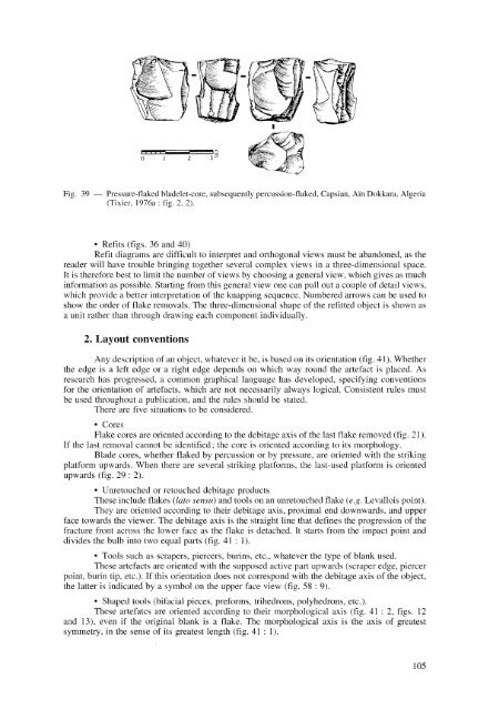
Fig. 39 — Pressure-flaked bladelet-core, subsequently percussion-flaked, Capsian, Ai'n Dokkara, Algeria<br />
(Tixier, 1976a: fig. 2, 2).<br />
• Refits (figs. 36 <strong>and</strong> 40)<br />
Refit diagrams are difficult to interpret <strong>and</strong> orthogonal views must be ab<strong>and</strong>oned, as the<br />
reader will have trouble bringing together several complex views in a three-dimensional space.<br />
It is therefore best to limit the number <strong>of</strong> views by choosing a general view, which gives as much<br />
information as possible. Starting from this general view one can pull out a couple <strong>of</strong> detail views,<br />
which provide a better interpretation <strong>of</strong> the knapping sequence. Numbered arrows can be used to<br />
show the order <strong>of</strong> flake removals. The three-dimensional shape <strong>of</strong> the refitted object is shown as<br />
a unit rather than through drawing each component individually.<br />
2. Layout convention s<br />
Any description <strong>of</strong> an object, whatever it be, is based on its orientation (fig. 41). Whether<br />
the edge is a left edge or a right edge depends on which way round the artefact is placed. As<br />
research has progressed, a common graphical language has developed, specifying conventions<br />
for the orientation <strong>of</strong> artefacts, which are not necessarily always logical. Consistent rules must<br />
be used throughout a publication, <strong>and</strong> the rules should be stated.<br />
There are five situations to be considered.<br />
• Cores<br />
Flake cores are oriented according to the debitage axis <strong>of</strong> the last flake removed (fig. 21).<br />
If the last removal cannot be identified; the core is oriented according to its morphology.<br />
Blade cores, whether flaked by percussion or by pressure, are oriented with the striking<br />
platform upwards. When there are several striking platforms, the last-used platform is oriented<br />
upwards (fig. 29 : 2).<br />
• Unretouched or retouched debitage products<br />
These include flakes (lato sensu) <strong>and</strong> tools on an unretouched flake (e.g. Levallois point).<br />
They are oriented according to their debitage axis, proximal end downwards, <strong>and</strong> upper<br />
face towards the viewer. The debitage axis is the straight line that defines the progression <strong>of</strong> the<br />
fracture front across the lower face as the flake is detached. It starts from the impact point <strong>and</strong><br />
divides the bulb into two equal parts (fig. 41 : 1).<br />
• Tools such as scrapers, piercers, burins, etc., whatever the type <strong>of</strong> blank used.<br />
These artefacts are oriented with the supposed active part upwards (scraper edge, piercer<br />
point, burin tip, etc.). If this orientation does not correspond with the debitage axis <strong>of</strong> the object,<br />
the latter is indicated by a symbol on the upper face view (fig. 58 : 9).<br />
• Shaped tools (bifacial pieces, preforms, trihedrons, polyhedrons, etc.).<br />
These artefatcs are oriented according to their morphological axis (fig. 41 : 2, figs. 12<br />
<strong>and</strong> 13), even if the original blank is a flake. The morphological axis is the axis <strong>of</strong> greatest<br />
symmetry, in the sense <strong>of</strong> its greatest length (fig. 41:1).<br />
105