FONIX® FP35 Touch - Frye Electronics
FONIX® FP35 Touch - Frye Electronics
FONIX® FP35 Touch - Frye Electronics

Create successful ePaper yourself
Turn your PDF publications into a flip-book with our unique Google optimized e-Paper software.
4 FONIX <strong>FP35</strong> Hearing Aid Analyzer<br />
[NEXT] [BACK] Moves back and forth between screens that are in a sequences.<br />
Examples include menus and the real-ear measurement screens.<br />
[p q] Moves the cursor up and down in a menu screen and in the<br />
Audiogram Entry screen. Adjusts the level of the source amplitude in<br />
a measurement screen.<br />
[t u] Cycles through available menu choices, adjusts the frequency selection<br />
in a single tone measurement, and adjusts the amplitude levels<br />
in an audiogram in the Audiogram Entry screen.<br />
[START/STOP] Starts or stops the current selected function.<br />
[OPERATE] Powers up and down the analyzer. When powered down, the LCD<br />
display is turned off and all data is cleared, but the main power is not<br />
turned off. The green LED will flash once every 3 seconds.<br />
[RESET] Interrupts any current running measurement and returns the <strong>FP35</strong><br />
to the Opening Screen. [RESET] will not clear leveling or calibration,<br />
but it will clear any data you have collected.<br />
[HELP] Pops up a help window containing instructions for the current screen.<br />
[PRINT/FEED] Prints the current screen when you press and release this key. Feeds<br />
the thermal paper when you press and hold this key.<br />
Connector:<br />
The <strong>FP35</strong> main board was revised in late October 2008 (the “-09 revision”). This added<br />
a new microphone connector on the front of the analyzer labeled “Mic” for the integrated<br />
real-ear microphone. The coupler microphone (and the old style real-ear microphone)<br />
is connected inside the sound chamber.<br />
<strong>Touch</strong> Screen:<br />
The <strong>FP35</strong> <strong>Touch</strong> features a touch screen LCD that allows you to perform many actions<br />
using your finger or a stylus directly on the built-in display. See Section 2.1.5 for<br />
details.<br />
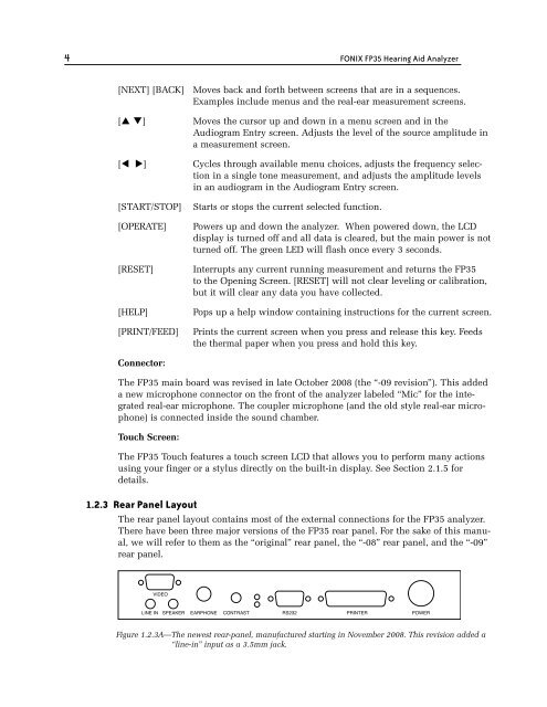
1.2.3 Rear Panel Layout<br />
The rear panel layout contains most of the external connections for the <strong>FP35</strong> analyzer.<br />
There have been three major versions of the <strong>FP35</strong> rear panel. For the sake of this manual,<br />
we will refer to them as the “original” rear panel, the “-08” rear panel, and the “-09”<br />
rear panel.<br />
VIDEO<br />
LINE IN SPEAKER EARPHONE CONTRAST RS232 PRINTER POWER<br />
Figure 1.2.3A—The newest rear-panel, manufactured starting in November 2008. This revision added a<br />
“line-in” input as a 3.5mm jack.