FONIX® FP35 Touch - Frye Electronics
FONIX® FP35 Touch - Frye Electronics
FONIX® FP35 Touch - Frye Electronics

You also want an ePaper? Increase the reach of your titles
YUMPU automatically turns print PDFs into web optimized ePapers that Google loves.
Coupler Measurements 79<br />
Confusion with Terminology<br />
With the new testing technology of hearing aid analyzers combined with the<br />
new technology of hearing aids, it’s easy to get terminology confused. <strong>Frye</strong><br />
<strong>Electronics</strong> has always used “noise reduction” to denote the averaging that<br />
the analyzer makes when analyzing data, as described in Section 2.5.1.3 and<br />
Section 2.5.2.3.<br />
Some high-end hearing aids have a function often referred to as “speech<br />
enhancement” or “noise reduction.” This function listens for continuous signals<br />
and lowers the gain of the hearing aid.<br />
Just keep in mind that these are two separate applications of the phrase “noise<br />
reduction” that mean two different things.<br />
3.8.2 Testing Directional Hearing Aids (<strong>FP35</strong> with Real Ear option only)<br />
At the most basic level, the function of directional hearing aids is to amplify<br />
sounds in front of the client while decreasing sounds behind the client, increasing<br />
his ability to listen to speech in a noisy environment. Perfect tests of directionality<br />
can only be performed in an anechoic chamber, something usually<br />
only available to hearing aid developers and researchers. However, you can use<br />
the <strong>FP35</strong> Analyzer to perform a basic check of directionality in order to verify<br />
that the directional microphones are functioning properly.<br />
To check directionality:<br />
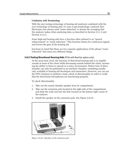
1. Take out the sound chamber speaker from its compartment.<br />
2. Take out the extension pole located in the right side of the compartment,<br />
and slide the wide end into the hole located on the bottom right corner of<br />
the analyzer.<br />
3. Install the speaker on the extension pole. See Figure 3.8.2A.<br />
Figure 3.8.2A—Speaker on the extension pole