FONIX® FP35 Touch - Frye Electronics
FONIX® FP35 Touch - Frye Electronics
FONIX® FP35 Touch - Frye Electronics

Create successful ePaper yourself
Turn your PDF publications into a flip-book with our unique Google optimized e-Paper software.
Coupler Measurements 65<br />
3.3 Hearing Aid Setup<br />
To set up the analyzer and the<br />
hearing aid for testing, you<br />
connect the hearing aid to a<br />
coupler. The standard couplers<br />
of the <strong>FP35</strong> analyzer are<br />
the HA-1 and HA-2 couplers.<br />
These couplers contain 2 cc of<br />
space, simulating the amount<br />
of space in a person’s ear canal.<br />
The procedure for connecting a<br />
hearing aid to those couplers is<br />
described in this section.<br />
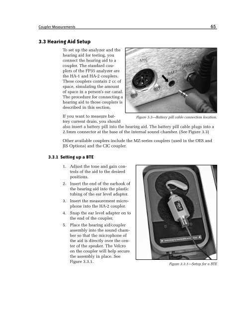
If you want to measure bat-<br />
Figure 3.3—Battery pill cable connection location.<br />
tery current drain, you should<br />
also insert a battery pill into the hearing aid. The battery pill cable plugs into a<br />
2.5mm connector at the base of the internal sound chamber. (See Figure 3.3)<br />
Other available couplers include the MZ-series couplers (used in the OES and<br />
JIS Options) and the CIC coupler.<br />
3.3.1 Setting up a BTE<br />
1. Adjust the tone and gain controls<br />
of the aid to the desired<br />
positions.<br />
2. Insert the end of the earhook of<br />
the hearing aid into the plastic<br />
tubing of the ear level adapter.<br />
3. Insert the measurement microphone<br />
into the HA-2 coupler.<br />
4. Snap the ear level adapter on to<br />
the end of the coupler.<br />
5. Place the hearing aid/coupler<br />
assembly into the sound chamber<br />
so that the microphone of<br />
the aid is directly over the center<br />
of the speaker. The Velcro<br />
on the coupler will help secure<br />
the assembly in place. See<br />
Figure 3.3.1.<br />
Figure 3.3.1—Setup for a BTE