The Design of Diagnostic Medical Facilities where ... - ResearchGate
The Design of Diagnostic Medical Facilities where ... - ResearchGate
The Design of Diagnostic Medical Facilities where ... - ResearchGate

You also want an ePaper? Increase the reach of your titles
YUMPU automatically turns print PDFs into web optimized ePapers that Google loves.
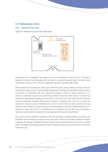
3.3 Radiography rooms<br />
3.3.1 General X‐ray room<br />
Figure 3.1: General X‐ray room with chest stand<br />
Staff entrance<br />
Chest stand<br />
and beam blocker<br />
Patient table<br />
Operator’s<br />
console area<br />
Radiation barrier<br />
(protective viewing screen)<br />
X<br />
X-ray<br />
tube<br />
Patient entrance<br />
A good layout for a radiographic room based on the two-corridor design is shown in Fig. 3.1. <strong>The</strong> room is<br />
designed for general X‐ray radiography with the facility to use either the patient table or the chest stand/<br />
vertical bucky. An area <strong>of</strong> 33 m 2 has been suggested for general X‐ray systems (BIR, 2000).<br />
<strong>The</strong> boundaries to all occupied areas (walls, doors, doorframes, floor, ceiling, windows, window frames and<br />
the protective viewing screen) must be shielded appropriately. Generally this requirement will be met by 2<br />
mm <strong>of</strong> lead, or its equivalent with other material (see Chapters 5 and 6). As noted in Section 6.1.1, in<br />
practice it is preferable to specify the actual British Standard Code <strong>of</strong> lead sheet required, to avoid errors<br />
arising from inappropriate rounding up or down later. In this case, Code 5 lead sheet (2.24 mm thickness)<br />
would be appropriate. Workload, distances and occupancy in adjoining areas may serve to reduce this<br />
requirement. However, a policy <strong>of</strong> shielding to the 2.24 mm (Code 5) level may reduce problems that may<br />
arise with future change <strong>of</strong> use and occupancy in the areas adjacent to the room. Notwithstanding this it is<br />
important to assess each room on an individual basis in consultation with an RPA. Also, as discussed in<br />
Section 6.2, walls should be marked with the lead equivalent thickness for future reference.<br />
<strong>The</strong> 2.24 mm (Code 5) shielding is adequate to deal with secondary or scattered radiation and assumes the<br />
boundaries will not normally be exposed to the primary beam. Where this may happen additional shielding<br />
is required, for example an additional lead beam blocker may be required behind a chest stand or vertical<br />
Bucky. This additional shielding should extend over the range <strong>of</strong> possible tube movements when it is directed<br />
towards the wall.<br />
20<br />
<strong>The</strong> <strong>Design</strong> <strong>of</strong> <strong>Diagnostic</strong> <strong>Medical</strong> <strong>Facilities</strong> <strong>where</strong> Ionising Radiation is used