The Design of Diagnostic Medical Facilities where ... - ResearchGate
The Design of Diagnostic Medical Facilities where ... - ResearchGate
The Design of Diagnostic Medical Facilities where ... - ResearchGate

You also want an ePaper? Increase the reach of your titles
YUMPU automatically turns print PDFs into web optimized ePapers that Google loves.
<strong>where</strong> Ḋ (0) is the product <strong>of</strong> the dose rate constant for the patient (0.092 μSvm 2 /MBqh for 18 F) and the<br />
administered activity A 0<br />
(MBq) and R tU<br />
is the reduction factor for the uptake time.<br />
Imaging room<br />
To calculate the dose from a patient during imaging, the decay during the uptake phase must be taken into<br />
account. In addition the reduction factor <strong>of</strong> 0.85 as a result <strong>of</strong> patient voiding should also be taken into<br />
account. <strong>The</strong> total dose (μSv) at a distance d (m) from the patient is given by<br />
F<br />
D(t<br />
i<br />
) = D(0)<br />
. × ti<br />
× Rti<br />
× 0.85 ×<br />
d<br />
u<br />
2<br />
Equation 5.11<br />
<strong>where</strong> Ḋ (0) is the product <strong>of</strong> the dose rate constant for the patient (0.092 μSv m 2 /MBqh) for 18 F and the<br />
administered activity A 0<br />
(MBq), R ti<br />
is the reduction factor for the imaging time t i<br />
and F u<br />
is the decay in the<br />
radionuclide activity since administration.<br />
To calculate the annual dose at a boundary, the calculated dose should be multiplied by the annual workload.<br />
<strong>The</strong> maximum allowable transmission can then be calculated using the dose constraint and occupancy<br />
factors in a similar manner to that employed in X‐ray.<br />
Shielding factors<br />
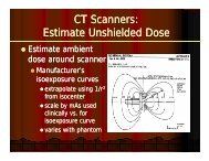
A variety <strong>of</strong> attenuation coefficients has been used to estimate transmission requirements for PET facilities.<br />
In some cases narrow-beam, good geometry attenuation coefficients for lead and concrete have been used.<br />
However, calculations based on these values will not provide sufficient shielding since they neglect scatter<br />
buildup factors. <strong>The</strong> AAPM recommends using values <strong>of</strong> broad beam transmission factors for lead, concrete,<br />
and iron that are based on consistent Monte Carlo calculations. Plots <strong>of</strong> the broad beam transmission at 511<br />
keV are given in Appendix D for lead and concrete. <strong>The</strong> transmission factors for 18 F through lead and concrete<br />
are also given.<br />
5.3 Examples <strong>of</strong> shielding calculations<br />
Examples <strong>of</strong> shielding calculations for radiology, nuclear medicine and PET facilities are presented in Sections<br />
5.3.1 and 5.3.2. <strong>The</strong> aim <strong>of</strong> the radiology examples is to show how the BIR and NCRP methodologies may be<br />
applied in particular cases using the dose constraints in Table 2.1 and other local data. In practice it may be<br />
prudent in marginal cases to calculate the shielding requirements using both methodologies. <strong>The</strong> examples are<br />
provided for illustrative purposes only and are not intended to substitute for the RPA’s assessment.<br />
<strong>The</strong> <strong>Design</strong> <strong>of</strong> <strong>Diagnostic</strong> <strong>Medical</strong> <strong>Facilities</strong> <strong>where</strong> Ionising Radiation is used 65