The Design of Diagnostic Medical Facilities where ... - ResearchGate
The Design of Diagnostic Medical Facilities where ... - ResearchGate
The Design of Diagnostic Medical Facilities where ... - ResearchGate
You also want an ePaper? Increase the reach of your titles
YUMPU automatically turns print PDFs into web optimized ePapers that Google loves.
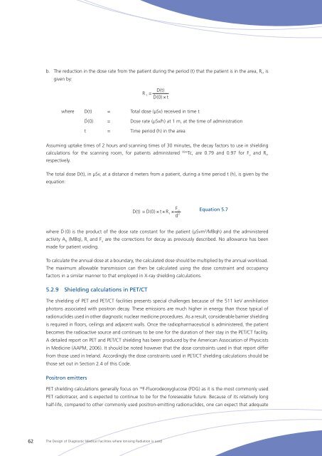
. <strong>The</strong> reduction in the dose rate from the patient during the period (t) that the patient is in the area, R t<br />
, is<br />
given by:<br />
R D(t)<br />
= . t D(0) × t<br />
<strong>where</strong> D(t) = Total dose (μSv) received in time t<br />
Ḋ(0) = Dose rate (μSv/h) at 1 m, at the time <strong>of</strong> administration<br />
t = Time period (h) in the area<br />
Assuming uptake times <strong>of</strong> 2 hours and scanning times <strong>of</strong> 30 minutes, the decay factors to use in shielding<br />
calculations for the scanning room, for patients administered 99m Tc, are 0.79 and 0.97 for F u<br />
and R t<br />
,<br />
respectively.<br />
<strong>The</strong> total dose D(t), in μSv, at a distance d meters from a patient, during a time period t (h), is given by the<br />
equation:<br />
F<br />
D(t) = D(0)<br />
.<br />
× t × R<br />
t<br />
×<br />
d<br />
u<br />
2<br />
Equation 5.7<br />
<strong>where</strong> Ḋ (0) is the product <strong>of</strong> the dose rate constant for the patient (μSvm 2 /MBqh) and the administered<br />
activity A 0<br />
(MBq), R t<br />
and F u<br />
are the corrections for decay as previously described. No allowance has been<br />
made for patient voiding.<br />
To calculate the annual dose at a boundary, the calculated dose should be multiplied by the annual workload.<br />
<strong>The</strong> maximum allowable transmission can then be calculated using the dose constraint and occupancy<br />
factors in a similar manner to that employed in X‐ray shielding calculations.<br />
5.2.9 Shielding calculations in PET/CT<br />
<strong>The</strong> shielding <strong>of</strong> PET and PET/CT facilities presents special challenges because <strong>of</strong> the 511 keV annihilation<br />
photons associated with positron decay. <strong>The</strong>se emissions are much higher in energy than those typical <strong>of</strong><br />
radionuclides used in other diagnostic nuclear medicine procedures. As a result, considerable barrier shielding<br />
is required in floors, ceilings and adjacent walls. Once the radiopharmaceutical is administered, the patient<br />
becomes the radioactive source and continues to be one for the duration <strong>of</strong> their stay in the PET/CT facility.<br />
A detailed report on PET and PET/CT shielding has been produced by the American Association <strong>of</strong> Physicists<br />
in Medicine (AAPM, 2006). It should be noted however that the dose constraints used in that report differ<br />
from those used in Ireland. Accordingly the dose constraints used in PET/CT shielding calculations should be<br />
those set out in Section 2.4 <strong>of</strong> this Code.<br />
Positron emitters<br />
PET shielding calculations generally focus on 18 F-Fluorodeoxyglucose (FDG) as it is the most commonly used<br />
PET radiotracer, and is expected to continue to be for the foreseeable future. Because <strong>of</strong> its relatively long<br />
half-life, compared to other commonly used positron-emitting radionuclides, one can expect that adequate<br />
62<br />
<strong>The</strong> <strong>Design</strong> <strong>of</strong> <strong>Diagnostic</strong> <strong>Medical</strong> <strong>Facilities</strong> <strong>where</strong> Ionising Radiation is used


