The Design of Diagnostic Medical Facilities where ... - ResearchGate
The Design of Diagnostic Medical Facilities where ... - ResearchGate
The Design of Diagnostic Medical Facilities where ... - ResearchGate

Create successful ePaper yourself
Turn your PDF publications into a flip-book with our unique Google optimized e-Paper software.
For general rooms, the lead equivalence <strong>of</strong> the screen is typically 2 mm although 3-4 mm or more may be<br />
required for angiography suites and multi-slice CT installations. <strong>The</strong> minimum height should be 2 m (BIR,<br />
2000). <strong>The</strong> upper half is generally transparent and made <strong>of</strong> lead glass or lead acrylic to permit the operator<br />
to have a panoramic view <strong>of</strong> the room, good visibility <strong>of</strong> the patient, the X‐ray tube, warning lights on<br />
equipment (<strong>where</strong> fitted) and the doors. <strong>The</strong> design must ensure integrity at the joints between the panel<br />
sections, and the panels and lead glass (see Appendix E, Fig. E.7). Joints should be adequately shielded and<br />
the lead glass sheets/panels should be overlapped by 30-40 mm (BIR, 2000) or protected by a shielded joint<br />
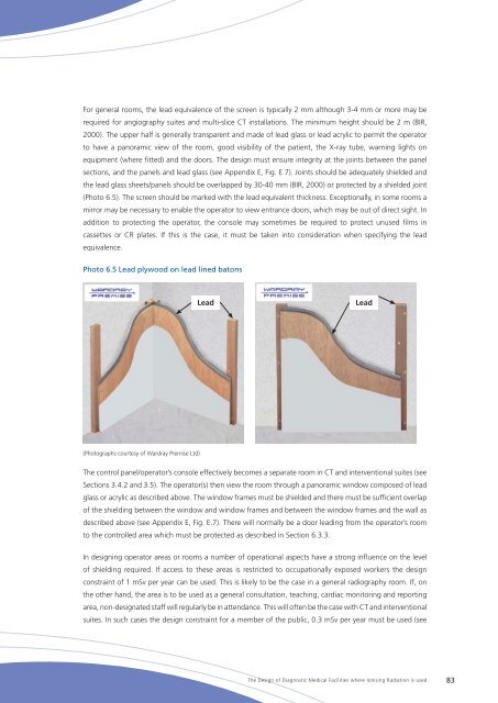
(Photo 6.5). <strong>The</strong> screen should be marked with the lead equivalent thickness. Exceptionally, in some rooms a<br />
mirror may be necessary to enable the operator to view entrance doors, which may be out <strong>of</strong> direct sight. In<br />
addition to protecting the operator, the console may sometimes be required to protect unused films in<br />
cassettes or CR plates. If this is the case, it must be taken into consideration when specifying the lead<br />
equivalence.<br />
Photo 6.5 Lead plywood on lead lined batons<br />
Lead<br />
Lead<br />
(Photographs courtesy <strong>of</strong> Wardray Premise Ltd)<br />
<strong>The</strong> control panel/operator’s console effectively becomes a separate room in CT and interventional suites (see<br />
Sections 3.4.2 and 3.5). <strong>The</strong> operator(s) then view the room through a panoramic window composed <strong>of</strong> lead<br />
glass or acrylic as described above. <strong>The</strong> window frames must be shielded and there must be sufficient overlap<br />
<strong>of</strong> the shielding between the window and window frames and between the window frames and the wall as<br />
described above (see Appendix E, Fig. E.7). <strong>The</strong>re will normally be a door leading from the operator’s room<br />
to the controlled area which must be protected as described in Section 6.3.3.<br />
In designing operator areas or rooms a number <strong>of</strong> operational aspects have a strong influence on the level<br />
<strong>of</strong> shielding required. If access to these areas is restricted to occupationally exposed workers the design<br />
constraint <strong>of</strong> 1 mSv per year can be used. This is likely to be the case in a general radiography room. If, on<br />
the other hand, the area is to be used as a general consultation, teaching, cardiac monitoring and reporting<br />
area, non-designated staff will regularly be in attendance. This will <strong>of</strong>ten be the case with CT and interventional<br />
suites. In such cases the design constraint for a member <strong>of</strong> the public, 0.3 mSv per year must be used (see<br />
<strong>The</strong> <strong>Design</strong> <strong>of</strong> <strong>Diagnostic</strong> <strong>Medical</strong> <strong>Facilities</strong> <strong>where</strong> Ionising Radiation is used 83