The Design of Diagnostic Medical Facilities where ... - ResearchGate
The Design of Diagnostic Medical Facilities where ... - ResearchGate
The Design of Diagnostic Medical Facilities where ... - ResearchGate

Create successful ePaper yourself
Turn your PDF publications into a flip-book with our unique Google optimized e-Paper software.
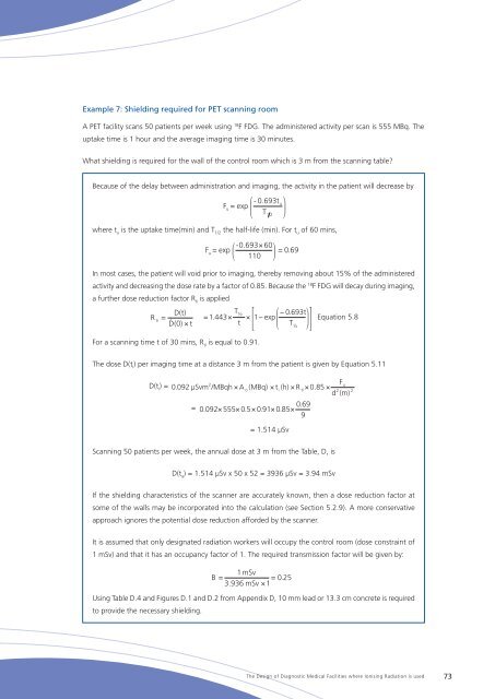
Example 7: Shielding required for PET scanning room<br />
A PET facility scans 50 patients per week using 18 F FDG. <strong>The</strong> administered activity per scan is 555 MBq. <strong>The</strong><br />
uptake time is 1 hour and the average imaging time is 30 minutes.<br />
What shielding is required for the wall <strong>of</strong> the control room which is 3 m from the scanning table<br />
Because <strong>of</strong> the delay between administration and imaging, the activity in the patient will decrease by<br />
F = exp<br />
u<br />
- 0.693t<br />
T<br />
1 2<br />
u<br />
<strong>where</strong> t u<br />
is the uptake time(min) and T 1/2<br />
the half-life (min). For t u<br />
<strong>of</strong> 60 mins,<br />
-0.693×<br />
60<br />
F u<br />
= exp<br />
= 0.69<br />
110<br />
In most cases, the patient will void prior to imaging, thereby removing about 15% <strong>of</strong> the administered<br />
activity and decreasing the dose rate by a factor <strong>of</strong> 0.85. Because the 18 F FDG will decay during imaging,<br />
a further dose reduction factor R ti<br />
is applied<br />
D(t)<br />
= .<br />
D(0)<br />
R t i<br />
×<br />
t<br />
T<br />
= 1.443×<br />
t<br />
For a scanning time t <strong>of</strong> 30 mins, R ti<br />
is equal to 0.91.<br />
½<br />
× 1−<br />
exp<br />
− 0.693t<br />
T<br />
½<br />
Equation 5.8<br />
<strong>The</strong> dose D(t i<br />
) per imaging time at a distance 3 m from the patient is given by Equation 5.11<br />
D(t i<br />
) =<br />
2<br />
Fu<br />
0 .092 μSvm /MBqh × A<br />
o<br />
(MBq) × ti<br />
(h) × R<br />
ti<br />
× 0.85 ×<br />
2<br />
d (m)<br />
=<br />
0.69<br />
0 .092×<br />
555×<br />
0.5 × 0.91×<br />
0.85×<br />
9<br />
= 1.514 μSv<br />
2<br />
Scanning 50 patients per week, the annual dose at 3 m from the Table, D, is<br />
D(t a<br />
) = 1.514 μSv x 50 x 52 = 3936 μSv = 3.94 mSv<br />
If the shielding characteristics <strong>of</strong> the scanner are accurately known, then a dose reduction factor at<br />
some <strong>of</strong> the walls may be incorporated into the calculation (see Section 5.2.9). A more conservative<br />
approach ignores the potential dose reduction afforded by the scanner.<br />
It is assumed that only designated radiation workers will occupy the control room (dose constraint <strong>of</strong><br />
1 mSv) and that it has an occupancy factor <strong>of</strong> 1. <strong>The</strong> required transmission factor will be given by:<br />
B 1mSv<br />
=<br />
0.25<br />
3.936 mSv × 1<br />
=<br />
Using Table D.4 and Figures D.1 and D.2 from Appendix D, 10 mm lead or 13.3 cm concrete is required<br />
to provide the necessary shielding.<br />
<strong>The</strong> <strong>Design</strong> <strong>of</strong> <strong>Diagnostic</strong> <strong>Medical</strong> <strong>Facilities</strong> <strong>where</strong> Ionising Radiation is used 73