The Design of Diagnostic Medical Facilities where ... - ResearchGate
The Design of Diagnostic Medical Facilities where ... - ResearchGate
The Design of Diagnostic Medical Facilities where ... - ResearchGate

You also want an ePaper? Increase the reach of your titles
YUMPU automatically turns print PDFs into web optimized ePapers that Google loves.
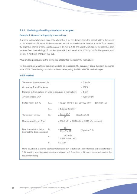
5.3.1 Radiology shielding calculation examples<br />
Example 1: General radiography room ceiling<br />
A general radiographic room has a ceiling height <strong>of</strong> 3 m. <strong>The</strong> distance from the patient table to the ceiling<br />
is 2 m. <strong>The</strong>re is an <strong>of</strong>fice directly above the room and it is assumed that the distance from the floor above to<br />
the organs <strong>of</strong> interest <strong>of</strong> the nearest occupant is 0.5 m (Fig. 5.1). <strong>The</strong> weekly workload for the room has been<br />
obtained from the Radiology Information System (RIS) and found to be 1000 Gy cm 2 for 300 patients, with<br />
average X‐ray beam energy <strong>of</strong> 100 kVp.<br />
What shielding is required in the ceiling to protect <strong>of</strong>fice workers in the room above<br />
For the ceiling, only scattered radiation needs to be considered. <strong>The</strong> occupancy above the room is assumed<br />
to be 100%. <strong>The</strong> shielding calculation is shown below, using the BIR and NCRP methodologies.<br />
a) BIR method<br />
<strong>The</strong> annual dose constraint, D c<br />
= 0.3 mSv<br />
Occupancy, T, in <strong>of</strong>fice above = 100%<br />
Distance, d, from patient on table to occupant in room above<br />
= 2.5 m<br />
Average weekly DAP = 1000 Gy cm 2<br />
Scatter factor at 1 m, S max<br />
= [(0.031 x kVp) + 2.5] μGy (Gy cm 2 ) -1 (Equation 5.3)<br />
S max<br />
= 5.6 μGy (Gy cm 2 ) -1<br />
<strong>The</strong> incident kerma,<br />
Unattenuated K inc<br />
at 2.5m<br />
K inc<br />
K<br />
S<br />
× DAP<br />
d<br />
max<br />
inc<br />
= (Equation 5.4)<br />
2<br />
= 896.0 μGy = 0.896 mGy ≡ 0.896 mSv per week<br />
Max. transmission factor, B =<br />
(to meet the dose constraint)<br />
K<br />
D<br />
c<br />
= B<br />
K × T × 52<br />
inc<br />
inc<br />
B = 0.0064<br />
D<br />
c<br />
0.3 mSv<br />
=<br />
× T × 52 0.896 mSv<br />
(Equation<br />
× 1×<br />
52<br />
5.5)<br />
0.3 mSv<br />
=<br />
0.896 mSv × 1×<br />
52<br />
Using equation 5.6 and the coefficients for secondary radiation at 100 kV for lead and concrete (Table<br />
5.7), a ceiling providing an attenuation equivalent to 1.2 mm lead or 80 mm concrete will provide the<br />
required shielding.<br />
66<br />
<strong>The</strong> <strong>Design</strong> <strong>of</strong> <strong>Diagnostic</strong> <strong>Medical</strong> <strong>Facilities</strong> <strong>where</strong> Ionising Radiation is used