DE2-115: User Manual
DE2-115: User Manual
DE2-115: User Manual

Create successful ePaper yourself
Turn your PDF publications into a flip-book with our unique Google optimized e-Paper software.
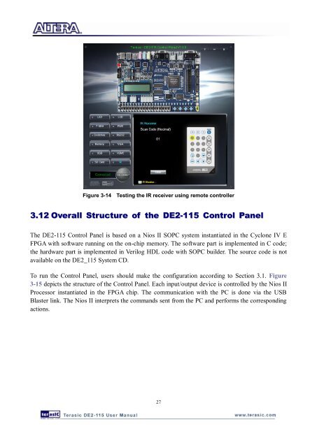
Figure 3-14 Testing the IR receiver using remote controller<br />
3.12 Overall Structure of the <strong>DE2</strong>-<strong>115</strong> Control Panel<br />
The <strong>DE2</strong>-<strong>115</strong> Control Panel is based on a Nios II SOPC system instantiated in the Cyclone IV E<br />
FPGA with software running on the on-chip memory. The software part is implemented in C code;<br />
the hardware part is implemented in Verilog HDL code with SOPC builder. The source code is not<br />
available on the <strong>DE2</strong>_<strong>115</strong> System CD.<br />
To run the Control Panel, users should make the configuration according to Section 3.1. Figure<br />
3-15 depicts the structure of the Control Panel. Each input/output device is controlled by the Nios II<br />
Processor instantiated in the FPGA chip. The communication with the PC is done via the USB<br />
Blaster link. The Nios II interprets the commands sent from the PC and performs the corresponding<br />
actions.<br />
27