DE2-115: User Manual
DE2-115: User Manual
DE2-115: User Manual

Create successful ePaper yourself
Turn your PDF publications into a flip-book with our unique Google optimized e-Paper software.
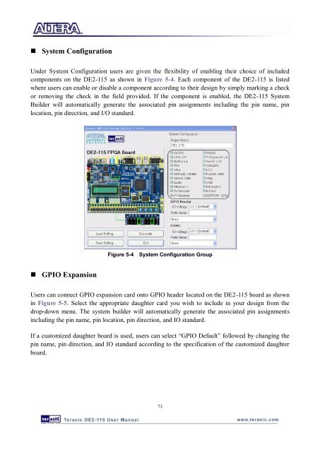
• System Configuration<br />
Under System Configuration users are given the flexibility of enabling their choice of included<br />
components on the <strong>DE2</strong>-<strong>115</strong> as shown in Figure 5-4. Each component of the <strong>DE2</strong>-<strong>115</strong> is listed<br />
where users can enable or disable a component according to their design by simply marking a check<br />
or removing the check in the field provided. If the component is enabled, the <strong>DE2</strong>-<strong>115</strong> System<br />
Builder will automatically generate the associated pin assignments including the pin name, pin<br />
location, pin direction, and I/O standard.<br />
Figure 5-4 System Configuration Group<br />
• GPIO Expansion<br />
<strong>User</strong>s can connect GPIO expansion card onto GPIO header located on the <strong>DE2</strong>-<strong>115</strong> board as shown<br />
in Figure 5-5. Select the appropriate daughter card you wish to include in your design from the<br />
drop-down menu. The system builder will automatically generate the associated pin assignments<br />
including the pin name, pin location, pin direction, and IO standard.<br />
If a customized daughter board is used, users can select “GPIO Default” followed by changing the<br />
pin name, pin direction, and IO standard according to the specification of the customized daughter<br />
board.<br />
73