Scientific and Technical Aerospace Reports Volume 38 July 28, 2000
Scientific and Technical Aerospace Reports Volume 38 July 28, 2000
Scientific and Technical Aerospace Reports Volume 38 July 28, 2000
You also want an ePaper? Increase the reach of your titles
YUMPU automatically turns print PDFs into web optimized ePapers that Google loves.
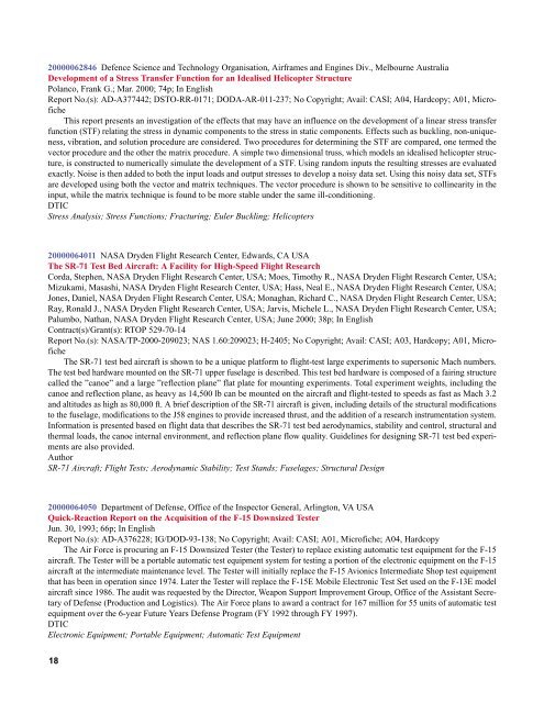
<strong>2000</strong>006<strong>28</strong>46 Defence Science <strong>and</strong> Technology Organisation, Airframes <strong>and</strong> Engines Div., Melbourne Australia<br />
Development of a Stress Transfer Function for an Idealised Helicopter Structure<br />
Polanco, Frank G.; Mar. <strong>2000</strong>; 74p; In English<br />
Report No.(s): AD-A377442; DSTO-RR-0171; DODA-AR-011-237; No Copyright; Avail: CASI; A04, Hardcopy; A01, Microfiche<br />
This report presents an investigation of the effects that may have an influence on the development of a linear stress transfer<br />
function (STF) relating the stress in dynamic components to the stress in static components. Effects such as buckling, non-uniqueness,<br />
vibration, <strong>and</strong> solution procedure are considered. Two procedures for determining the STF are compared, one termed the<br />
vector procedure <strong>and</strong> the other the matrix procedure. A simple two dimensional truss, which models an idealised helicopter structure,<br />
is constructed to numerically simulate the development of a STF. Using r<strong>and</strong>om inputs the resulting stresses are evaluated<br />
exactly. Noise is then added to both the input loads <strong>and</strong> output stresses to develop a noisy data set. Using this noisy data set, STFs<br />
are developed using both the vector <strong>and</strong> matrix techniques. The vector procedure is shown to be sensitive to collinearity in the<br />
input, while the matrix technique is found to be more stable under the same ill-conditioning.<br />
DTIC<br />
Stress Analysis; Stress Functions; Fracturing; Euler Buckling; Helicopters<br />
<strong>2000</strong>0064011 NASA Dryden Flight Research Center, Edwards, CA USA<br />
The SR-71 Test Bed Aircraft: A Facility for High-Speed Flight Research<br />
Corda, Stephen, NASA Dryden Flight Research Center, USA; Moes, Timothy R., NASA Dryden Flight Research Center, USA;<br />
Mizukami, Masashi, NASA Dryden Flight Research Center, USA; Hass, Neal E., NASA Dryden Flight Research Center, USA;<br />
Jones, Daniel, NASA Dryden Flight Research Center, USA; Monaghan, Richard C., NASA Dryden Flight Research Center, USA;<br />
Ray, Ronald J., NASA Dryden Flight Research Center, USA; Jarvis, Michele L., NASA Dryden Flight Research Center, USA;<br />
Palumbo, Nathan, NASA Dryden Flight Research Center, USA; June <strong>2000</strong>; <strong>38</strong>p; In English<br />
Contract(s)/Grant(s): RTOP 529-70-14<br />
Report No.(s): NASA/TP-<strong>2000</strong>-209023; NAS 1.60:209023; H-2405; No Copyright; Avail: CASI; A03, Hardcopy; A01, Microfiche<br />
The SR-71 test bed aircraft is shown to be a unique platform to flight-test large experiments to supersonic Mach numbers.<br />
The test bed hardware mounted on the SR-71 upper fuselage is described. This test bed hardware is composed of a fairing structure<br />
called the ”canoe” <strong>and</strong> a large ”reflection plane” flat plate for mounting experiments. Total experiment weights, including the<br />
canoe <strong>and</strong> reflection plane, as heavy as 14,500 lb can be mounted on the aircraft <strong>and</strong> flight-tested to speeds as fast as Mach 3.2<br />
<strong>and</strong> altitudes as high as 80,000 ft. A brief description of the SR-71 aircraft is given, including details of the structural modifications<br />
to the fuselage, modifications to the J58 engines to provide increased thrust, <strong>and</strong> the addition of a research instrumentation system.<br />
Information is presented based on flight data that describes the SR-71 test bed aerodynamics, stability <strong>and</strong> control, structural <strong>and</strong><br />
thermal loads, the canoe internal environment, <strong>and</strong> reflection plane flow quality. Guidelines for designing SR-71 test bed experiments<br />
are also provided.<br />
Author<br />
SR-71 Aircraft; Flight Tests; Aerodynamic Stability; Test St<strong>and</strong>s; Fuselages; Structural Design<br />
<strong>2000</strong>0064050 Department of Defense, Office of the Inspector General, Arlington, VA USA<br />
Quick-Reaction Report on the Acquisition of the F-15 Downsized Tester<br />
Jun. 30, 1993; 66p; In English<br />
Report No.(s): AD-A3762<strong>28</strong>; IG/DOD-93-1<strong>38</strong>; No Copyright; Avail: CASI; A01, Microfiche; A04, Hardcopy<br />
The Air Force is procuring an F-15 Downsized Tester (the Tester) to replace existing automatic test equipment for the F-15<br />
aircraft. The Tester will be a portable automatic test equipment system for testing a portion of the electronic equipment on the F-15<br />
aircraft at the intermediate maintenance level. The Tester will initially replace the F-15 Avionics Intermediate Shop test equipment<br />
that has been in operation since 1974. Later the Tester will replace the F-15E Mobile Electronic Test Set used on the F-13E model<br />
aircraft since 1986. The audit was requested by the Director, Weapon Support Improvement Group, Office of the Assistant Secretary<br />
of Defense (Production <strong>and</strong> Logistics). The Air Force plans to award a contract for 167 million for 55 units of automatic test<br />
equipment over the 6-year Future Years Defense Program (FY 1992 through FY 1997).<br />
DTIC<br />
Electronic Equipment; Portable Equipment; Automatic Test Equipment<br />
18


