

ComputerAided_Design_Engineering_amp_Manufactur.pdf
ComputerAided_Design_Engineering_amp_Manufactur.pdf
ComputerAided_Design_Engineering_amp_Manufactur.pdf

You also want an ePaper? Increase the reach of your titles
YUMPU automatically turns print PDFs into web optimized ePapers that Google loves.
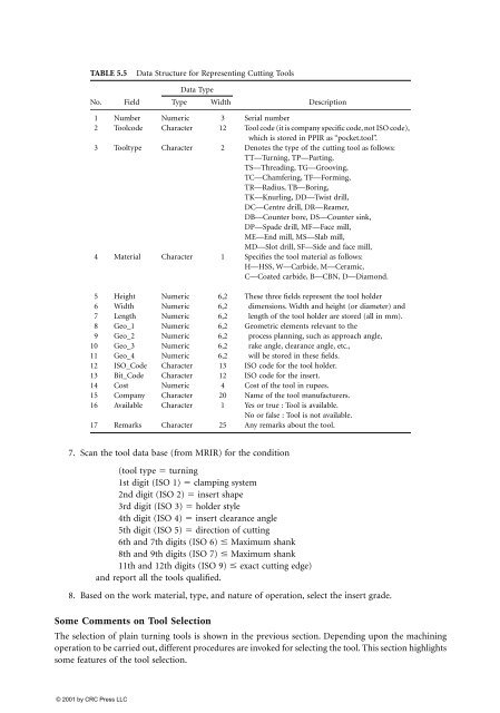
TABLE 5.5 Data Structure for Representing Cutting Tools<br />
No. Field<br />
Data Type<br />
Type Width<br />
7. Scan the tool data base (from MRIR) for the condition<br />
(tool type � turning<br />
1st digit (ISO 1) � cl<strong>amp</strong>ing system<br />
2nd digit (ISO 2) � insert shape<br />
3rd digit (ISO 3) � holder style<br />
4th digit (ISO 4) � insert clearance angle<br />
5th digit (ISO 5) � direction of cutting<br />
6th and 7th digits (ISO 6) � Maximum shank<br />
8th and 9th digits (ISO 7) � Maximum shank<br />
11th and 12th digits (ISO 9) � exact cutting edge)<br />
and report all the tools qualified.<br />
Description<br />
1 Number Numeric 3 Serial number<br />
2 Toolcode Character 12 Tool code (it is company specific code, not ISO code),<br />
which is stored in PPIR as “pocket.tool”.<br />
3 Tooltype Character 2 Denotes the type of the cutting tool as follows:<br />
TT—Turning, TP—Parting,<br />
TS—Threading, TG—Grooving,<br />
TC—Chamfering, TF—Forming,<br />
TR—Radius, TB—Boring,<br />
TK—Knurling, DD—Twist drill,<br />
DC—Centre drill, DR—Reamer,<br />
DB—Counter bore, DS—Counter sink,<br />
DP—Spade drill, MF—Face mill,<br />
ME—End mill, MS—Slab mill,<br />
MD—Slot drill, SF—Side and face mill,<br />
4 Material Character 1 Specifies the tool material as follows:<br />
H—HSS, W—Carbide, M—Ceramic,<br />
C—Coated carbide, B—CBN, D—Diamond.<br />
5 Height Numeric 6,2 These three fields represent the tool holder<br />
6 Width Numeric 6,2 dimensions. Width and height (or diameter) and<br />
7 Length Numeric 6,2 length of the tool holder are stored (all in mm).<br />
8 Geo_1 Numeric 6,2 Geometric elements relevant to the<br />
9 Geo_2 Numeric 6,2 process planning, such as approach angle,<br />
10 Geo_3 Numeric 6,2 rake angle, clearance angle, etc.,<br />
11 Geo_4 Numeric 6,2 will be stored in these fields.<br />
12 ISO_Code Character 13 ISO code for the tool holder.<br />
13 Bit_Code Character 12 ISO code for the insert.<br />
14 Cost Numeric 4 Cost of the tool in rupees.<br />
15 Company Character 20 Name of the tool manufacturers.<br />
16 Available Character 1 Yes or true : Tool is available.<br />
No or false : Tool is not available.<br />
17 Remarks Character 25 Any remarks about the tool.<br />
8. Based on the work material, type, and nature of operation, select the insert grade.<br />
Some Comments on Tool Selection<br />
The selection of plain turning tools is shown in the previous section. Depending upon the machining<br />
operation to be carried out, different procedures are invoked for selecting the tool. This section highlights<br />
some features of the tool selection.


