

ComputerAided_Design_Engineering_amp_Manufactur.pdf
ComputerAided_Design_Engineering_amp_Manufactur.pdf
ComputerAided_Design_Engineering_amp_Manufactur.pdf

Create successful ePaper yourself
Turn your PDF publications into a flip-book with our unique Google optimized e-Paper software.
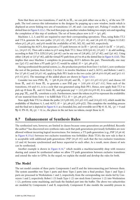
Note that there are two transitions, t7 and t8, in , we can pick either one as the of the new TPpath.<br />
The tool conveys this information to the designer by popping up a new window, inside which is<br />
displayed an arrow linking two sets of transitions: {t7, t8} and—(an empty set). Picking t7 results in the<br />
dotted lines in Figure 8.12(c). The tool then pops up another window linking two empty sets and signaling<br />
the completion of this step of synthesis. The set of home places now is H � {p1, p8}.<br />
Machines 1, 2, 3, and R2 are required to start their corresponding operations. Thus, using Rules TT.2<br />
and TT.4, generate the new paths: [t3 p12 t2], [t8 p9 t7], [t5 p11 t4], and [t6 p10 t5] (Figure 8.12(d))<br />
where p12, p9, p11, and p10 model the availability of M1, M2, R2, and M3, respectively.<br />
Considering the AGV1, first generate a TT-path between t4 (in � � [p4 t4]) and t3 (in �� � [t3 p4]),<br />
i.e., [t4 p13 t3]. Then add a token to p13 using Rule TT.2. Since LEX([p4 t4], [t3 p4]) � �, add nothing,<br />
according to Rule TT.4. LEX([t3 p4], [p4 t4]) can be any one of {[t8 p8]}, {[t7 p7 t8]}, and {[p1 t6]}. Using<br />
either {[t8 p4} or {[t7 p7 t8]}, add the virtual PT-path from p13 to t8 as the dotted line in Figure 8.12(d). This<br />
implies that once Machine 2 completes its processing, AGV1 delivers the part. Theoretically, one may<br />
use {[p2 t7]} and then a PT-path [p13 t7] would be added. H � {p1, p8–p13}.<br />
Having synthesized the partial system, i.e., the production portion from Enry 1 to Exit 1, now synthesize<br />
the rest of the portion, from Entry 2 to Exit 2, to involve Machines 4 and 5, AGV2, and Robots 1 and 2.<br />
For [t7 p8 t1] and [t5 p11 t4], applying Rule PP.1 leads to the two cycles [p8 t9 p14 t10 p8] and [p11 t11<br />
p15 t12 p11]. The meanings of the added places are shown in Figure 12(e).<br />
Consider two new PSPs: �4 � [p8 t9 p14 t10 p8] and �5 � [p11 t11 p15 t12 p11] and choose t10<br />
from �4 and t11 from �5 to generate a new PSP, psp � [t10 p16 t13 p17 t11]. Note each of the<br />
transitions, t10 and t11, is in a cycle that was generated using Rule PP.1. Hence, now apply Rule TT.3 to<br />
pick up t9 from �4 and t12 from �5 and generate psp’ � [t12 p18 t14 p19 t9]. It is easily verified that<br />
psp, psp,’ �4 , and �5 constitute a cycle. Furthermore, insert the tokens in p19 to represent the availability<br />
of raw material from Entry 1 to fulfill Rule TT.2. H � {p1, p8–p13, p19}.<br />
Now apply Rule TT.2 to obtain the paths: [t13 p20 t10], [t11 p21 t13], and [t14 p22 t12], which model the<br />
availability of Machines 4, 5, and AGV2. H � {p1, p8–p13, p19–p22}. This completes the modeling process<br />
and the final net is depicted in Figure 8.11 as a bounded, live, and reversible net if �p � H, M0 (p) � 0 and<br />
�p � PN-H, (p) � 0; i.e., the places in the net have no tokens, except those in H.<br />
8.7 Enhancement of Synthesis Rules<br />
The synthesized nets, however, are limited in classes because some generations are prohibited. Recently<br />
the author 34 has discovered new synthesis rules such that path generations previously forbidden are now<br />
allowed without incurring logical incorrectness. For instance, a TT-path generation (e.g., PSP [t3 p4 t4]<br />
in Figure 8.13(a)) between two exclusive transitions was forbidden (Rule TT.0); the new rule is that it<br />
is acceptable with additional path generations (PSP [t4 p5 t3]) such that the two exclusive transitions<br />
(t3 and t4) become synchronized and hence sequential to each other. As a result, more classes of nets<br />
can be synthesized.<br />
Another ex<strong>amp</strong>le is shown in Figure 8.14, 27 which models a machine/assembly shop with resource<br />
sharing and cannot be synthesized unless we allow TT-path generations between exclusive transitions<br />
and extend the rules to GPNs. In the sequel, we explain the model and develop the rules for both.<br />
The Model<br />
M 0<br />
� 3<br />
The net model consists of three parts: Components I and II and the interconnecting part between them.<br />
The system assembles two Type-1 parts and three Type-2 parts into a final product. Type-1 and Type-2<br />
parts are processed in Workstations 1 and 2, respectively, from the corresponding raw stocks fed by Conveyors<br />
1 and 2, respectively. Robot 1 (3) loads Type-1 (2) raw stock from Conveyor 1 (2) into Workstation<br />
1 (2), performs some machining, and loads the finished part into the buffer. The above two subactivities<br />
are modeled by Components I and II, respectively. Component II also models the assembly process in<br />
t g


