

ComputerAided_Design_Engineering_amp_Manufactur.pdf
ComputerAided_Design_Engineering_amp_Manufactur.pdf
ComputerAided_Design_Engineering_amp_Manufactur.pdf

You also want an ePaper? Increase the reach of your titles
YUMPU automatically turns print PDFs into web optimized ePapers that Google loves.
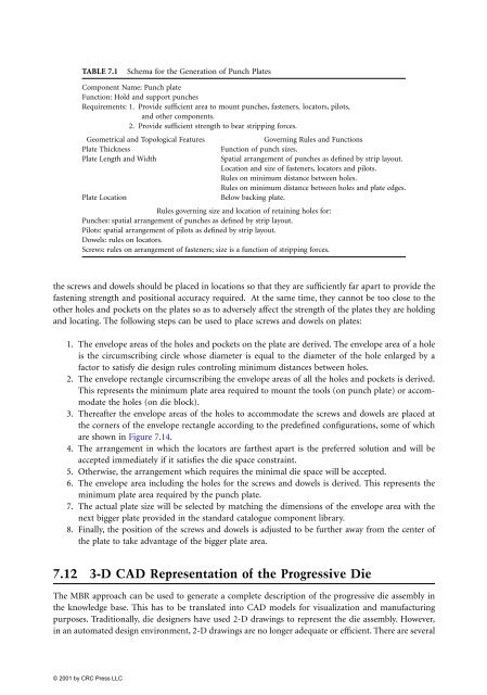
TABLE 7.1<br />
Schema for the Generation of Punch Plates<br />
Component Name: Punch plate<br />
Function: Hold and support punches<br />
Requirements: 1. Provide sufficient area to mount punches, fasteners, locators, pilots,<br />
and other components.<br />
2. Provide sufficient strength to bear stripping forces.<br />
Geometrical and Topological Features Governing Rules and Functions<br />
Plate Thickness Function of punch sizes.<br />
Plate Length and Width Spatial arrangement of punches as defined by strip layout.<br />
Location and size of fasteners, locators and pilots.<br />
Rules on minimum distance between holes.<br />
Rules on minimum distance between holes and plate edges.<br />
Plate Location Below backing plate.<br />
Rules governing size and location of retaining holes for:<br />
Punches: spatial arrangement of punches as defined by strip layout.<br />
Pilots: spatial arrangement of pilots as defined by strip layout.<br />
Dowels: rules on locators.<br />
Screws: rules on arrangement of fasteners; size is a function of stripping forces.<br />
the screws and dowels should be placed in locations so that they are sufficiently far apart to provide the<br />
fastening strength and positional accuracy required. At the same time, they cannot be too close to the<br />
other holes and pockets on the plates so as to adversely affect the strength of the plates they are holding<br />
and locating. The following steps can be used to place screws and dowels on plates:<br />
1. The envelope areas of the holes and pockets on the plate are derived. The envelope area of a hole<br />
is the circumscribing circle whose diameter is equal to the diameter of the hole enlarged by a<br />
factor to satisfy die design rules controling minimum distances between holes.<br />
2. The envelope rectangle circumscribing the envelope areas of all the holes and pockets is derived.<br />
This represents the minimum plate area required to mount the tools (on punch plate) or accommodate<br />
the holes (on die block).<br />
3. Thereafter the envelope areas of the holes to accommodate the screws and dowels are placed at<br />
the corners of the envelope rectangle according to the predefined configurations, some of which<br />
are shown in Figure 7.14.<br />
4. The arrangement in which the locators are farthest apart is the preferred solution and will be<br />
accepted immediately if it satisfies the die space constraint.<br />
5. Otherwise, the arrangement which requires the minimal die space will be accepted.<br />
6. The envelope area including the holes for the screws and dowels is derived. This represents the<br />
minimum plate area required by the punch plate.<br />
7. The actual plate size will be selected by matching the dimensions of the envelope area with the<br />
next bigger plate provided in the standard catalogue component library.<br />
8. Finally, the position of the screws and dowels is adjusted to be further away from the center of<br />
the plate to take advantage of the bigger plate area.<br />
7.12 3-D CAD Representation of the Progressive Die<br />
The MBR approach can be used to generate a complete description of the progressive die assembly in<br />
the knowledge base. This has to be translated into CAD models for visualization and manufacturing<br />
purposes. Traditionally, die designers have used 2-D drawings to represent the die assembly. However,<br />
in an automated design environment, 2-D drawings are no longer adequate or efficient. There are several


