

ComputerAided_Design_Engineering_amp_Manufactur.pdf
ComputerAided_Design_Engineering_amp_Manufactur.pdf
ComputerAided_Design_Engineering_amp_Manufactur.pdf

Create successful ePaper yourself
Turn your PDF publications into a flip-book with our unique Google optimized e-Paper software.
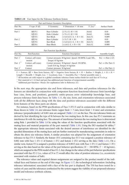
TABLE 1.10 User Input for the Tolerance Synthesis System<br />
Part and Feature Geometry Description<br />
Part No. F type (F-id) F Geometry F Dimension � 10 mm F . Loc‡<br />
Surface Finish<br />
Part-1 Bff(F1) Base-Cylinder [2.75,1.5] (R � H) [0,0,0] 0.01<br />
Nff(F2) Hole-Cylinder [1.75,1.5] (R � H) [0,0,0] 0.004<br />
Nff(F3) Slot-Block [1.5,0.5,0.5] (L � B � H) [0,0,15] 0.009<br />
Part-2 Bff(F4) Base-Cylinder [1.75,7] (R � H) [0,0,0] 0.01<br />
Nff(F5) Slot-Block [1.5,0.5,0.5] (L � B � H) [0,0,15] 0.009<br />
Part-3 Bff(F6) Base-Block [1,1,0.5] (L � B � H) [0,0,15] 0.009<br />
Part No. Part/Function<br />
Part Function Specification<br />
Function Description Assembly Graph<br />
Part Contact, self-rotary Contact pressure: 30 kg/mm<br />
motion<br />
2 , Speed: 350 RPM, Load: NIL, Pa1 → (Part-2 �)<br />
Torque: 65 kg�mm<br />
Part Contact, self-rotary Contact pressure: 30 kg/mm<br />
motion<br />
2 , Speed: 350 RPM,<br />
Pa2 → (Pa1 Part-3)<br />
Load: 0.45 kg, Torque: 65 kg�mm<br />
Part Contact Contact pressure: 30 kg/mm2 2<br />
Pa3 → (Pa2 Part-1)<br />
†�<br />
3 †<br />
1 †<br />
F � Feature, Bff � Base form feature, Nff � Negative form feature, R � H � Radius � Height, L � B � H �<br />
Length � Breadth � Height, Loc. � Locations, Assy. � Assembly, Pax � Partial assembly state x.<br />
‡ All locations are with respect to a global coordinate reference frame surface finish for each face of F is in �.<br />
† Part material is C-14 Steel and part has additional part function of nonpermanent assembly.<br />
�<br />
Additional part function—House (for explanation refer to Reference 22).<br />
In the next step, the appropriate size and form tolerances, and data and position tolerances for the<br />
features are identified in conjunction with component function-functional tolerance limit knowledge<br />
base (size, form, and position), geometric entity-process error relationship knowledge base, and<br />
process-tolerance limit data bases. In Table 1.11, the size, form, and orientation tolerances associated<br />
with all the different faces along with the data and position tolerances associated with the different<br />
form features of the three parts are shown.<br />
For instance, based on the PFM specifications of Face 3 (F3-3) and in conjunction with rules similar to<br />
those shown in Table 1.8, size tolerance limits (upper limit � 7 mm, lower limit � 0 mm) and orientation<br />
tolerance (perpendicularity) of 0.001 mm are assigned (Table 1.11) on the face. The size tolerance limits are<br />
derived by first identifying the type of fit between the two mating faces. In this case, face F3-3 maintains an<br />
interference fit with the mating face. The amount of interference between the two mating faces is determined<br />
using Rule 1 provided in Table 1.8 by using the values of the function specifications associated with the<br />
mating faces and material properties of the part material (Table 1.10). Using the ISO standard fit tables, 23<br />
the appropriate tolerance limits associated with the desired amount of interference are identified for the<br />
specified dimensions of the mating faces and are further restricted by manufacturing constraints in order to<br />
obtain the above size tolerance limits. A similar procedure was adopted for the assignment of orientation<br />
tolerance to face F3-3. Similarly, the feature (F3) containing face F3-3 was assigned a position tolerance of<br />
0.002 mm with Face 1 (F1-1) of feature 1 (F1) and feature 2 (F2) serving as the data (Table 1.11). On a<br />
similar note, feature F2 is assigned a position tolerance of 0.0015 mm with Face 1 (F1-1) and feature 1 (F1)<br />
serving as the data based on the values of the part behavior specifications (N � 350 RPM, T � 65 kg/mm),<br />
which are assigned to the PFM model of face F2-2. Any change in the values of the part behavior specifications<br />
associated with face F2-2 (i.e., values of N or T) would affect the value of position tolerance (i.e., eccentricity<br />
associated with rotation of hub).<br />
The tolerance values and required datum assignments are assigned to the product model of the individual<br />
faces and features at the end of this stage. In Figure 1.17, the technological information (including<br />
tolerance information) associated with a face of the key part is displayed. The TSS has been tested for a<br />
variety of cases and the tolerances synthesized by the system suggest the viability of our proposed tolerance<br />
model and tolerance synthesis schema.<br />
© 2001 by CRC Press LLC


