

ComputerAided_Design_Engineering_amp_Manufactur.pdf
ComputerAided_Design_Engineering_amp_Manufactur.pdf
ComputerAided_Design_Engineering_amp_Manufactur.pdf

You also want an ePaper? Increase the reach of your titles
YUMPU automatically turns print PDFs into web optimized ePapers that Google loves.
SIG3= -1013.3<br />
END J SDIR=0.00000E+00 SBZ= -1.7041 SBY=<br />
382.49 SIG1= 384.19 SIG3= -384.19<br />
STATIC FORCES ON NODE 1 0.000000E+00 12500.0<br />
0.184741E-12 0.000000E+00 299991. 562500.<br />
0.00000E+00 0.00000E+00 3-D BEAM 4<br />
END I SDIR=0.00000E+00 SBZ= -1.7041 SBY=<br />
382.49 SIG1= 384.19 SIG3= -384.19<br />
END J SDIR=0.00000E+00 SBZ= -1.5837 SBY=<br />
-246.50 SIG1= 248.08 SIG3= -248.08<br />
STATIC FORCES ON NODE 2 0.000000E+00 12500.0<br />
-0.113687E-12 0.000000E+00 299991. 225000.<br />
STATIC FORCES ON NODE 3 0.000000E+00 -12500.0<br />
-0.113687E-12 0.000000E+00 -299991. 112500.<br />
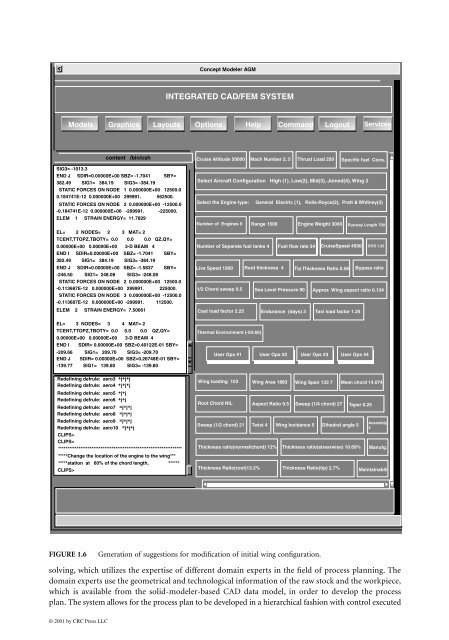
FIGURE 1.6<br />
solving, which utilizes the expertise of different domain experts in the field of process planning. The<br />
domain experts use the geometrical and technological information of the raw stock and the workpiece,<br />
which is available from the solid-modeler-based CAD data model, in order to develop the process<br />
plan. The system allows for the process plan to be developed in a hierarchical fashion with control executed<br />
© 2001 by CRC Press LLC<br />
INTEGRATED CAD/FEM SYSTEM<br />
Models Graphics Layouts Options Help Command Logout Services<br />
content /bin/csh<br />
STATIC FORCES ON NODE 2 0.000000E+00 -12500.0<br />
-0.184741E-12 0.000000E+00 -299991. -225000.<br />
ELEM 1 STRAIN ENERGY= 11.7829<br />
EL= 2 NODES= 2 3 MAT= 2<br />
TCENT,TTOPZ,TBOTY= 0.0 0.0 0.0 QZ,QY=<br />
ELEM 2 STRAIN ENERGY= 7.50061<br />
EL= 3 NODES= 3 4 MAT= 2<br />
TCENT,TTOPZ,TBOTY= 0.0 0.0 0.0 QZ,QY=<br />
0.00000E+00 0.00000E+00 3-D BEAM 4<br />
END I SDIR= 0.00000E+00 SBZ=0.40122E-01 SBY=<br />
-209.66 SIG1= 209.70 SIG3= -209.70<br />
END J SDIR= 0.00000E+00 SBZ=0.26748E-01 SBY=<br />
-139.77 SIG1= 139.80 SIG3= -139.80<br />
Redefining defrule: aero3 +j+j+j<br />
Redefining defrule: aero4 +j+j+j<br />
Redefining defrule: aero5 +j+j<br />
Redefining defrule: aero6 +j+j<br />
Redefining defrule: aero7 =j+j+j<br />
Redefining defrule: aero8 =j+j+j<br />
Redefining defrule: aero9 =j+j+j<br />
Redefining defrule: aero10 =j+j+j<br />
CLIPS><br />
CLIPS><br />
*******************************************************************<br />
*****Change the location of the engine to the wing***<br />
*****station at 60% of the chord length, ******<br />
CLIPS><br />
Concept Modeler AGM<br />
Cruise Altitude 50000 Mach Number 2, 5 Thrust Load 250<br />
Select Aircraft Configuration High (1), Low(2), Mid(3), Joined(4), Wing 2<br />
Select the Engine type: General Electric (1), Rolls-Royce(2), Pratt & Whitney(3)<br />
Number of Engines 0 Range 1500 Engine Weight 3000 Runway Length 700<br />
Number of Separate fuel tanks 4 Fuel flow rate 34 CruiseSpeed 4500 EOS 1.25<br />
Live Speed 1900 Root thickness 4 Tip Thickness Ratio 0.56<br />
1/2 Chord sweep 0.5<br />
Sea Level Pressure 90<br />
Cast load factor 2.25 Endurance (days) 3 Taxi load factor 1.25<br />
Thermal Environment (-50:60)<br />
Generation of suggestions for modification of initial wing configuration.<br />
Specific fuel Cons.<br />
Bypass ratio<br />
Approx Wing aspect ratio 0.134<br />
User Ops #1 User Ops #2 User Ops #3 User Ops #4<br />
Wing loading 103 Wing Area 1883 Wing Span 133 7 Mean chord 14.074<br />
Root Chord NIL Aspect Ratio 9.5 Sweep (1/4 chord) 27 Taper 0.25<br />
Sweep (1/2 chord) 21 Twist 4 Wing Incidence 5 Dihedral angle 5<br />
Thickness ratio(normal/chord) 12%<br />
Thickness ratio(strearwise) 10.69% Manufg.<br />
Thickness Ratio(root)13.2% Thickness Ratio(tip) 2.7%<br />
Assembly<br />
2<br />
Maintainabili


