

ComputerAided_Design_Engineering_amp_Manufactur.pdf
ComputerAided_Design_Engineering_amp_Manufactur.pdf
ComputerAided_Design_Engineering_amp_Manufactur.pdf

Create successful ePaper yourself
Turn your PDF publications into a flip-book with our unique Google optimized e-Paper software.
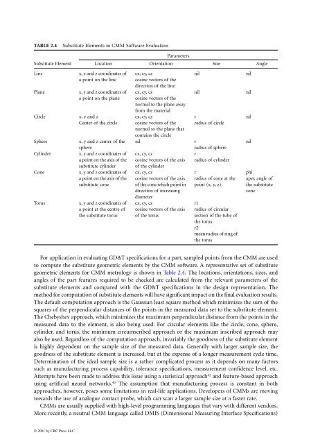
TABLE 2.4 Substitute Elements in CMM Software Evaluation<br />
Substitute Element<br />
Line x, y and z coordinates of<br />
a point on the line<br />
Plane x, y and z coordinates of<br />
a point on the plane<br />
Circle x, y and z<br />
Center of the circle<br />
Sphere x, y and z center of the<br />
sphere<br />
Cylinder x, y and z coordinates of<br />
a point on the axis of the<br />
substitute cylinder<br />
Cone x, y and z coordinates of<br />
a point on the axis of the<br />
substitute cone<br />
Torus x, y and z coordinates of<br />
a point at the centre of<br />
the substitute torus<br />
For application in evaluating GD&T specifications for a part, s<strong>amp</strong>led points from the CMM are used<br />
to compute the substitute geometric elements by the CMM software. A representative set of substitute<br />
geometric elements for CMM metrology is shown in Table 2.4. The locations, orientations, sizes, and<br />
angles of the part features required to be checked are calculated from the relevant parameters of the<br />
substitute elements and compared with the GD&T specifications in the design representation. The<br />
method for computation of substitute elements will have significant impact on the final evaluation results.<br />
The default computation approach is the Gaussian least square method which minimizes the sum of the<br />
squares of the perpendicular distances of the points in the measured data set to the substitute element.<br />
The Chebyshev approach, which minimizes the maximum perpendicular distance from the points in the<br />
measured data to the element, is also being used. For circular elements like the circle, cone, sphere,<br />
cylinder, and torus, the minimum circumscribed approach or the maximum inscribed approach may<br />
also be used. Regardless of the computation approach, invariably the goodness of the substitute element<br />
is highly dependent on the s<strong>amp</strong>le size of the measured data. Generally with larger s<strong>amp</strong>le size, the<br />
goodness of the substitute element is increased, but at the expense of a longer measurement cycle time.<br />
Determination of the ideal s<strong>amp</strong>le size is a rather complicated process as it depends on many factors<br />
such as manufacturing process capability, tolerance specifications, measurement confidence level, etc.<br />
Attempts have been made to address this issue using a statistical approach 42 and feature-based approach<br />
using artificial neural networks. 43 The assumption that manufacturing process is constant in both<br />
approaches, however, poses some limitations in real-life applications. Developers of CMMs are moving<br />
towards the use of analogue contact probe, which can scan a larger s<strong>amp</strong>le size at a faster rate.<br />
CMMs are usually supplied with high-level programming languages that vary with different vendors.<br />
More recently, a neutral CMM language called DMIS (Dimensional Measuring Interface Specifications)<br />
© 2001 by CRC Press LLC<br />
Location<br />
Parameters<br />
Orientation Size Angle<br />
cx, cy, cz<br />
cosine vectors of the<br />
direction of the line<br />
cx, cy, cz<br />
cosine vectors of the<br />
normal to the plane away<br />
from the material<br />
cx, cy, cz<br />
cosine vectors of the<br />
normal to the plane that<br />
contains the circle<br />
nil nil<br />
nil nil<br />
r<br />
radius of circle<br />
nil r<br />
radius of sphere<br />
cx, cy, cz<br />
r<br />
cosine vectors of the axis radius of cylinder<br />
of the cylinder<br />
cx, cy, cz<br />
r<br />
cosine vectors of the axis radius of cone at the<br />
of the cone which point in point (x, y, z)<br />
direction of increasing<br />
diameter<br />
cx, cy, cz<br />
r1<br />
cosine vectors of the axis radius of circular<br />
of the torus<br />
section of the tube of<br />
the torus<br />
r2<br />
mean radius of ring of<br />
the torus<br />
nil<br />
nil<br />
phi<br />
apex angle of<br />
the substitute<br />
cone


