

ComputerAided_Design_Engineering_amp_Manufactur.pdf
ComputerAided_Design_Engineering_amp_Manufactur.pdf
ComputerAided_Design_Engineering_amp_Manufactur.pdf

You also want an ePaper? Increase the reach of your titles
YUMPU automatically turns print PDFs into web optimized ePapers that Google loves.
y a revolute joint. By selecting aligned and against as post-spatial relationships, the user defines the<br />
desired kinematic pair {d,e} and initiates the solution process for this inverse kinematics problem. Further<br />
input required is the selection of those parts that are fixed to the ground, i.e., the bases a and e.<br />
Once the user has specified the spatial relationships between the components of the mechanism, local<br />
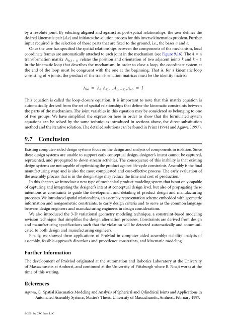
coordinate frames are automatically attached to each joint in the mechanism (see Figure 9.16). The 4 � 4<br />
transformation matrix Ak( k� 1)<br />
relates the position and orientation of two adjacent joints k and k + 1<br />
in the kinematic loop that describes the mechanism. In order to close a loop, the coordinate system at<br />
the end of the loop must be congruent with the one at the beginning. That is, for a kinematic loop<br />
consisting of n joints, the product of the transformation matrices must be the identity matrix:<br />
This equation is called the loop-closure equation. It is important to note that this matrix equation is<br />
automatically derived from the set of spatial relationships that define the kinematic constraints between<br />
the parts of the mechanism. The joint variables in this equation may be considered as belonging to one<br />
of two groups. We have simplified the expression here in order to show that the formulated system<br />
equations can be solved by the same techniques introduced in sections above, the direct substitution<br />
method and the iterative solution. The detailed solutions can be found in Prinz (1994) and Aguwa (1997).<br />
9.7 Conclusion<br />
Existing computer-aided design systems focus on the design and analysis of components in isolation. Since<br />
these design systems are unable to support early conceptual design, designer’s intent cannot be captured,<br />
represented, and propagated to down-stream activities. The consequence of this inability is that existing<br />
design systems are not capable of optimizing the product against life-cycle constraints. Assembly is the final<br />
manufacturing stage and is also the most complicated and cost-effective process. The early evaluation of<br />
the assembly process that is in the design stage may reduce the time and cost of production.<br />
In this chapter, we introduce a new type of mechanical product modeling system that is not only capable<br />
of capturing and integrating the designer’s intent at conceptual design level, but also of propagating these<br />
intentions as constraints to guide the development and detailing of product design and manufacturing<br />
processes. We introduced spatial relationships, an assembly representation scheme embedded with geometric<br />
information and nongeometric constraints, to carry design criteria and to serve as the common language<br />
between design engineers and manufacturing engineers in design considerations.<br />
We also introduced the 3-D variational geometry modeling technique, a constraint-based modeling<br />
revision technique that simplifies the design alternation processes. Constraints are derived from design<br />
and manufacturing specifications such that the violation will be detected automatically and communicated<br />
to both design and manufacturing engineers.<br />
Finally, we showed three applications of ProMod in computer-aided assembly: stability analysis of<br />
assembly, feasible-approach directions and precedence constraints, and kinematic modeling.<br />
Further Information<br />
The development of ProMod originated at the Automation and Robotics Laboratory at the University<br />
of Massachusetts at Amherst, and continued at the University of Pittsburgh where B. Nnaji works at the<br />
time of this writing.<br />
References<br />
Aguwa, C., Spatial Kinematics Modeling and Analysis of Spherical and Cylindrical Joints and Applications in<br />
Automated Assembly Systems, Master’s Thesis, University of Massachusetts, Amherst, February 1997.<br />
© 2001 by CRC Press LLC<br />
A00 � A01A12…A n � 1 �<br />
( )nA n0 I


