PIC16F8X, 18-Pin FLASH/EEPROM 8-Bit MCU Data Sheet - Microchip
PIC16F8X, 18-Pin FLASH/EEPROM 8-Bit MCU Data Sheet - Microchip
PIC16F8X, 18-Pin FLASH/EEPROM 8-Bit MCU Data Sheet - Microchip
You also want an ePaper? Increase the reach of your titles
YUMPU automatically turns print PDFs into web optimized ePapers that Google loves.
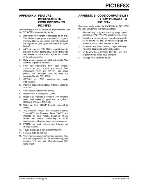
APPENDIX A: FEATURE<br />
IMPROVEMENTS -<br />
FROM PIC16C5X TO<br />
<strong>PIC16F8X</strong><br />
The following is the list of feature improvements over<br />
the PIC16C5X microcontroller family:<br />
1. Instruction word length is increased to 14 bits.<br />
This allows larger page sizes both in program<br />
memory (2K now as opposed to 512 before) and<br />
the register file (128 bytes now versus 32 bytes<br />
before).<br />
2. A PC latch register (PCLATH) is added to handle<br />
program memory paging. PA2, PA1 and PA0 bits<br />
are removed from the status register and placed<br />
in the option register.<br />
3. <strong>Data</strong> memory paging is redefined slightly. The<br />
STATUS register is modified.<br />
4. Four new instructions have been added:<br />
RETURN, RETFIE, ADDLW, and SUBLW. Two<br />
instructions, TRIS and OPTION, are being<br />
phased out although they are kept for<br />
compatibility with PIC16C5X.<br />
5. OPTION and TRIS registers are made<br />
6.<br />
addressable.<br />
Interrupt capability is added. Interrupt vector is<br />
at 0004h.<br />
7. Stack size is increased to 8 deep.<br />
8. Reset vector is changed to 0000h.<br />
9. Reset of all registers is revisited. Five different<br />
reset (and wake-up) types are recognized.<br />
Registers are reset differently.<br />
10. Wake up from SLEEP through interrupt is<br />
added.<br />
11. Two separate timers, the Oscillator Start-up<br />
Timer (OST) and Power-up Timer (PWRT), are<br />
included for more reliable power-up. These<br />
timers are invoked selectively to avoid<br />
unnecessary delays on power-up and wake-up.<br />
12. PORTB has weak pull-ups and interrupt on<br />
change features.<br />
13. T0CKI pin is also a port pin (RA4/T0CKI).<br />
14. FSR is a full 8-bit register.<br />
15. "In system programming" is made possible. The<br />
user can program PIC16CXX devices using only<br />
five pins: VDD, VSS, VPP, RB6 (clock) and RB7<br />
(data in/out).<br />
<strong>PIC16F8X</strong><br />
APPENDIX B: CODE COMPATIBILITY<br />
- FROM PIC16C5X TO<br />
<strong>PIC16F8X</strong><br />
To convert code written for PIC16C5X to <strong>PIC16F8X</strong>,<br />
the user should take the following steps:<br />
1. Remove any program memory page select<br />
operations (PA2, PA1, PA0 bits) for CALL, GOTO.<br />
2. Revisit any computed jump operations (write to<br />
PC or add to PC, etc.) to make sure page bits<br />
are set properly under the new scheme.<br />
3. Eliminate any data memory page switching.<br />
Redefine data variables for reallocation.<br />
4. Verify all writes to STATUS, OPTION, and FSR<br />
registers since these have changed.<br />
5. Change reset vector to 0000h.<br />
© 1998 <strong>Microchip</strong> Technology Inc. DS30430C-page 115


