

PIC16F8X, 18-Pin FLASH/EEPROM 8-Bit MCU Data Sheet - Microchip
PIC16F8X, 18-Pin FLASH/EEPROM 8-Bit MCU Data Sheet - Microchip
PIC16F8X, 18-Pin FLASH/EEPROM 8-Bit MCU Data Sheet - Microchip

Create successful ePaper yourself
Turn your PDF publications into a flip-book with our unique Google optimized e-Paper software.
<strong>PIC16F8X</strong><br />
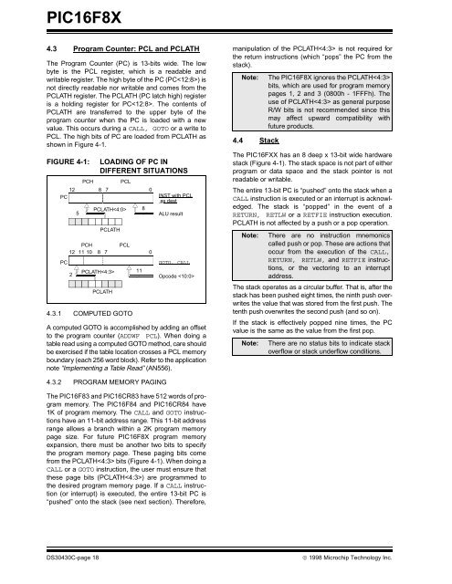
4.3 Program Counter: PCL and PCLATH<br />
The Program Counter (PC) is 13-bits wide. The low<br />
byte is the PCL register, which is a readable and<br />
writable register. The high byte of the PC (PC) is<br />
not directly readable nor writable and comes from the<br />
PCLATH register. The PCLATH (PC latch high) register<br />
is a holding register for PC. The contents of<br />
PCLATH are transferred to the upper byte of the<br />
program counter when the PC is loaded with a new<br />
value. This occurs during a CALL, GOTO or a write to<br />
PCL. The high bits of PC are loaded from PCLATH as<br />
shown in Figure 4-1.<br />
FIGURE 4-1: LOADING OF PC IN<br />
DIFFERENT SITUATIONS<br />
PCH PCL<br />
12 8 7 0<br />
PC<br />
PC<br />
5<br />
PCLATH<br />
PCLATH<br />
PCH PCL<br />
12 11 10 8 7<br />
0<br />
2<br />
PCLATH<br />
PCLATH<br />
4.3.1 COMPUTED GOTO<br />
A computed GOTO is accomplished by adding an offset<br />
to the program counter (ADDWF PCL). When doing a<br />
table read using a computed GOTO method, care should<br />
be exercised if the table location crosses a PCL memory<br />
boundary (each 256 word block). Refer to the application<br />
note “Implementing a Table Read” (AN556).<br />
4.3.2 PROGRAM MEMORY PAGING<br />
INST with PCL<br />
as dest<br />
ALU result<br />
GOTO, CALL<br />
Opcode <br />
The PIC16F83 and PIC16CR83 have 512 words of program<br />
memory. The PIC16F84 and PIC16CR84 have<br />
1K of program memory. The CALL and GOTO instructions<br />
have an 11-bit address range. This 11-bit address<br />
range allows a branch within a 2K program memory<br />
page size. For future <strong>PIC16F8X</strong> program memory<br />
expansion, there must be another two bits to specify<br />
the program memory page. These paging bits come<br />
from the PCLATH bits (Figure 4-1). When doing a<br />
CALL or a GOTO instruction, the user must ensure that<br />
these page bits (PCLATH) are programmed to<br />
the desired program memory page. If a CALL instruction<br />
(or interrupt) is executed, the entire 13-bit PC is<br />
“pushed” onto the stack (see next section). Therefore,<br />
11<br />
8<br />
manipulation of the PCLATH is not required for<br />
the return instructions (which “pops” the PC from the<br />
stack).<br />
Note: The <strong>PIC16F8X</strong> ignores the PCLATH<br />
bits, which are used for program memory<br />
pages 1, 2 and 3 (0800h - 1FFFh). The<br />
use of PCLATH as general purpose<br />
R/W bits is not recommended since this<br />
may affect upward compatibility with<br />
future products.<br />
4.4 Stack<br />
The PIC16FXX has an 8 deep x 13-bit wide hardware<br />
stack (Figure 4-1). The stack space is not part of either<br />
program or data space and the stack pointer is not<br />
readable or writable.<br />
The entire 13-bit PC is “pushed” onto the stack when a<br />
CALL instruction is executed or an interrupt is acknowledged.<br />
The stack is “popped” in the event of a<br />
RETURN, RETLW or a RETFIE instruction execution.<br />
PCLATH is not affected by a push or a pop operation.<br />
Note: There are no instruction mnemonics<br />
called push or pop. These are actions that<br />
occur from the execution of the CALL,<br />
RETURN, RETLW, and RETFIE instructions,<br />
or the vectoring to an interrupt<br />
address.<br />
The stack operates as a circular buffer. That is, after the<br />
stack has been pushed eight times, the ninth push overwrites<br />
the value that was stored from the first push. The<br />
tenth push overwrites the second push (and so on).<br />
If the stack is effectively popped nine times, the PC<br />
value is the same as the value from the first pop.<br />
Note: There are no status bits to indicate stack<br />
overflow or stack underflow conditions.<br />
DS30430C-page <strong>18</strong> © 1998 <strong>Microchip</strong> Technology Inc.


