

PIC16F8X, 18-Pin FLASH/EEPROM 8-Bit MCU Data Sheet - Microchip
PIC16F8X, 18-Pin FLASH/EEPROM 8-Bit MCU Data Sheet - Microchip
PIC16F8X, 18-Pin FLASH/EEPROM 8-Bit MCU Data Sheet - Microchip

You also want an ePaper? Increase the reach of your titles
YUMPU automatically turns print PDFs into web optimized ePapers that Google loves.
<strong>PIC16F8X</strong><br />
8.9 Interrupts<br />
The <strong>PIC16F8X</strong> has 4 sources of interrupt:<br />
• External interrupt RB0/INT pin<br />
• TMR0 overflow interrupt<br />
• PORTB change interrupts (pins RB7:RB4)<br />
• <strong>Data</strong> <strong>EEPROM</strong> write complete interrupt<br />
The interrupt control register (INTCON) records<br />
individual interrupt requests in flag bits. It also contains<br />
the individual and global interrupt enable bits.<br />
The global interrupt enable bit, GIE (INTCON)<br />
enables (if set) all un-masked interrupts or disables (if<br />
cleared) all interrupts. Individual interrupts can be<br />
disabled through their corresponding enable bits in<br />
INTCON register. <strong>Bit</strong> GIE is cleared on reset.<br />
The “return from interrupt” instruction, RETFIE, exits<br />
interrupt routine as well as sets the GIE bit, which<br />
re-enable interrupts.<br />
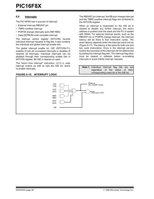
FIGURE 8-16: INTERRUPT LOGIC<br />
T0IF<br />
T0IE<br />
INTF<br />
INTE<br />
RBIF<br />
RBIE<br />
EEIF<br />
EEIE<br />
GIE<br />
The RB0/INT pin interrupt, the RB port change interrupt<br />
and the TMR0 overflow interrupt flags are contained in<br />
the INTCON register.<br />
When an interrupt is responded to; the GIE bit is<br />
cleared to disable any further interrupt, the return<br />
address is pushed onto the stack and the PC is loaded<br />
with 0004h. For external interrupt events, such as the<br />
RB0/INT pin or PORTB change interrupt, the interrupt<br />
latency will be three to four instruction cycles. The<br />
exact latency depends when the interrupt event occurs<br />
(Figure 8-17). The latency is the same for both one and<br />
two cycle instructions. Once in the interrupt service<br />
routine the source(s) of the interrupt can be determined<br />
by polling the interrupt flag bits. The interrupt flag bit(s)<br />
must be cleared in software before re-enabling<br />
interrupts to avoid infinite interrupt requests.<br />
Note 1: Individual interrupt flag bits are set<br />
regardless of the status of their<br />
corresponding mask bit or the GIE bit.<br />
Wake-up<br />
(If in SLEEP mode)<br />
Interrupt to CPU<br />
DS30430C-page 48 © 1998 <strong>Microchip</strong> Technology Inc.


