

PIC16F8X, 18-Pin FLASH/EEPROM 8-Bit MCU Data Sheet - Microchip
PIC16F8X, 18-Pin FLASH/EEPROM 8-Bit MCU Data Sheet - Microchip
PIC16F8X, 18-Pin FLASH/EEPROM 8-Bit MCU Data Sheet - Microchip

You also want an ePaper? Increase the reach of your titles
YUMPU automatically turns print PDFs into web optimized ePapers that Google loves.
<strong>PIC16F8X</strong><br />
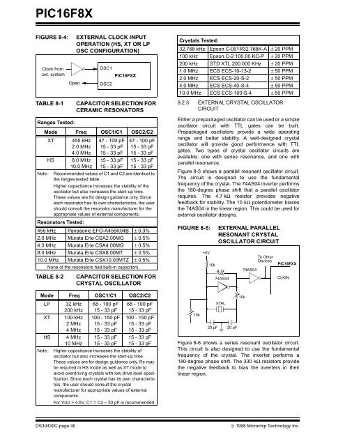
FIGURE 8-4: EXTERNAL CLOCK INPUT<br />
OPERATION (HS, XT OR LP<br />
OSC CONFIGURATION)<br />
Clock from<br />
OSC1<br />
ext. system PIC16FXX<br />
Open<br />
TABLE 8-1 CAPACITOR SELECTION FOR<br />
CERAMIC RESONATORS<br />
Ranges Tested:<br />
Mode Freq OSC1/C1 OSC2/C2<br />
XT 455 kHz<br />
2.0 MHz<br />
4.0 MHz<br />
HS 8.0 MHz<br />
10.0 MHz<br />
47 - 100 pF<br />
15 - 33 pF<br />
15 - 33 pF<br />
15 - 33 pF<br />
15 - 33 pF<br />
47 - 100 pF<br />
15 - 33 pF<br />
15 - 33 pF<br />
15 - 33 pF<br />
15 - 33 pF<br />
Note : Recommended values of C1 and C2 are identical to<br />
the ranges tested table.<br />
Higher capacitance increases the stability of the<br />
oscillator but also increases the start-up time.<br />
These values are for design guidance only. Since<br />
each resonator has its own characteristics, the user<br />
should consult the resonator manufacturer for the<br />
appropriate values of external components.<br />
Resonators Tested:<br />
455 kHz Panasonic EFO-A455K04B ± 0.3%<br />
2.0 MHz Murata Erie CSA2.00MG ± 0.5%<br />
4.0 MHz Murata Erie CSA4.00MG ± 0.5%<br />
8.0 MHz Murata Erie CSA8.00MT ± 0.5%<br />
10.0 MHz Murata Erie CSA10.00MTZ ± 0.5%<br />
None of the resonators had built-in capacitors.<br />
TABLE 8-2 CAPACITOR SELECTION FOR<br />
CRYSTAL OSCILLATOR<br />
Mode Freq OSC1/C1 OSC2/C2<br />
LP 32 kHz<br />
200 kHz<br />
XT 100 kHz<br />
2 MHz<br />
4 MHz<br />
HS 4 MHz<br />
10 MHz<br />
OSC2<br />
68 - 100 pF<br />
15 - 33 pF<br />
100 - 150 pF<br />
15 - 33 pF<br />
15 - 33 pF<br />
15 - 33 pF<br />
15 - 33 pF<br />
68 - 100 pF<br />
15 - 33 pF<br />
100 - 150 pF<br />
15 - 33 pF<br />
15 - 33 pF<br />
15 - 33 pF<br />
15 - 33 pF<br />
Note : Higher capacitance increases the stability of<br />
oscillator but also increases the start-up time.<br />
These values are for design guidance only. Rs may<br />
be required in HS mode as well as XT mode to<br />
avoid overdriving crystals with low drive level specification.<br />
Since each crystal has its own characteristics,<br />
the user should consult the crystal<br />
manufacturer for appropriate values of external<br />
components.<br />
For VDD > 4.5V, C1 = C2 ≈ 30 pF is recommended.<br />
Crystals Tested:<br />
32.768 kHz Epson C-001R32.768K-A ± 20 PPM<br />
100 kHz Epson C-2 100.00 KC-P ± 20 PPM<br />
200 kHz STD XTL 200.000 KHz ± 20 PPM<br />
1.0 MHz ECS ECS-10-13-2 ± 50 PPM<br />
2.0 MHz ECS ECS-20-S-2 ± 50 PPM<br />
4.0 MHz ECS ECS-40-S-4 ± 50 PPM<br />
10.0 MHz ECS ECS-100-S-4 ± 50 PPM<br />
8.2.3 EXTERNAL CRYSTAL OSCILLATOR<br />
CIRCUIT<br />
Either a prepackaged oscillator can be used or a simple<br />
oscillator circuit with TTL gates can be built.<br />
Prepackaged oscillators provide a wide operating<br />
range and better stability. A well-designed crystal<br />
oscillator will provide good performance with TTL<br />
gates. Two types of crystal oscillator circuits are<br />
available; one with series resonance, and one with<br />
parallel resonance.<br />
Figure 8-5 shows a parallel resonant oscillator circuit.<br />
The circuit is designed to use the fundamental<br />
frequency of the crystal. The 74AS04 inverter performs<br />
the <strong>18</strong>0-degree phase shift that a parallel oscillator<br />
requires. The 4.7 kΩ resistor provides negative<br />
feedback for stability. The 10 kΩ potentiometer biases<br />
the 74AS04 in the linear region. This could be used for<br />
external oscillator designs.<br />
FIGURE 8-5: EXTERNAL PARALLEL<br />
RESONANT CRYSTAL<br />
OSCILLATOR CIRCUIT<br />
Figure 8-6 shows a series resonant oscillator circuit.<br />
This circuit is also designed to use the fundamental<br />
frequency of the crystal. The inverter performs a<br />
<strong>18</strong>0-degree phase shift. The 330 kΩ resistors provide<br />
the negative feedback to bias the inverters in their<br />
linear region.<br />
DS30430C-page 40 © 1998 <strong>Microchip</strong> Technology Inc.<br />
10k<br />
+5V<br />
10k<br />
4.7k<br />
20 pF<br />
74AS04<br />
XTAL<br />
20 pF<br />
10k<br />
74AS04<br />
To Other<br />
Devices<br />
PIC16FXX<br />
CLKIN


