

PIC16F8X, 18-Pin FLASH/EEPROM 8-Bit MCU Data Sheet - Microchip
PIC16F8X, 18-Pin FLASH/EEPROM 8-Bit MCU Data Sheet - Microchip
PIC16F8X, 18-Pin FLASH/EEPROM 8-Bit MCU Data Sheet - Microchip

Create successful ePaper yourself
Turn your PDF publications into a flip-book with our unique Google optimized e-Paper software.
8.7 Time-out Sequence and Power-down<br />
Status <strong>Bit</strong>s (TO/PD)<br />
On power-up (Figure 8-10, Figure 8-11, Figure 8-12<br />
and Figure 8-13) the time-out sequence is as follows:<br />
First PWRT time-out is invoked after a POR has<br />
expired. Then the OST is activated. The total time-out<br />
will vary based on oscillator configuration and PWRTE<br />
configuration bit status. For example, in RC mode with<br />
the PWRT disabled, there will be no time-out at all.<br />
TABLE 8-5 TIME-OUT IN VARIOUS<br />
SITUATIONS<br />
Oscillator<br />
Configuration<br />
PWRT<br />
Enabled<br />
Power-up Wake-up<br />
PWRT<br />
Disabled<br />
from<br />
SLEEP<br />
XT, HS, LP 72 ms +<br />
1024TOSC<br />
1024TOSC 1024TOSC<br />
RC 72 ms — —<br />
Since the time-outs occur from the POR reset pulse, if<br />
MCLR is kept low long enough, the time-outs will<br />
expire. Then bringing MCLR high, execution will begin<br />
immediately (Figure 8-10). This is useful for testing<br />
purposes or to synchronize more than one <strong>PIC16F8X</strong><br />
device when operating in parallel.<br />
Table 8-6 shows the significance of the TO and PD bits.<br />
Table 8-3 lists the reset conditions for some special<br />
registers, while Table 8-4 lists the reset conditions for<br />
all the registers.<br />
TABLE 8-6 STATUS BITS AND THEIR<br />
SIGNIFICANCE<br />
TO PD Condition<br />
1 1 Power-on Reset<br />
0 x Illegal, TO is set on POR<br />
x 0 Illegal, PD is set on POR<br />
0 1 WDT Reset (during normal operation)<br />
0 0 WDT Wake-up<br />
1 1 MCLR Reset during normal operation<br />
1 0 MCLR Reset during SLEEP or interrupt<br />
wake-up from SLEEP<br />
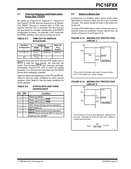
8.8 Reset on Brown-Out<br />
<strong>PIC16F8X</strong><br />
A brown-out is a condition where device power (VDD)<br />
dips below its minimum value, but not to zero, and then<br />
recovers. The device should be reset in the event of a<br />
brown-out.<br />
To reset a <strong>PIC16F8X</strong> device when a brown-out occurs,<br />
external brown-out protection circuits may be built, as<br />
shown in Figure 8-14 and Figure 8-15.<br />
FIGURE 8-14: BROWN-OUT PROTECTION<br />
CIRCUIT 1<br />
This circuit will activate reset when VDD goes below<br />
(Vz + 0.7V) where Vz = Zener voltage.<br />
FIGURE 8-15: BROWN-OUT PROTECTION<br />
CIRCUIT 2<br />
© 1998 <strong>Microchip</strong> Technology Inc. DS30430C-page 47<br />
33k<br />
VDD<br />
VDD<br />
R1<br />
R2<br />
10k<br />
40k<br />
VDD<br />
MCLR<br />
<strong>PIC16F8X</strong><br />
This brown-out circuit is less expensive, although less<br />
accurate. Transistor Q1 turns off when VDD is below a<br />
certain level such that:<br />
VDD •<br />
Q1<br />
40k<br />
R1<br />
R1 + R2<br />
VDD<br />
MCLR<br />
<strong>PIC16F8X</strong><br />
= 0.7V


