

PIC16F8X, 18-Pin FLASH/EEPROM 8-Bit MCU Data Sheet - Microchip
PIC16F8X, 18-Pin FLASH/EEPROM 8-Bit MCU Data Sheet - Microchip
PIC16F8X, 18-Pin FLASH/EEPROM 8-Bit MCU Data Sheet - Microchip

You also want an ePaper? Increase the reach of your titles
YUMPU automatically turns print PDFs into web optimized ePapers that Google loves.
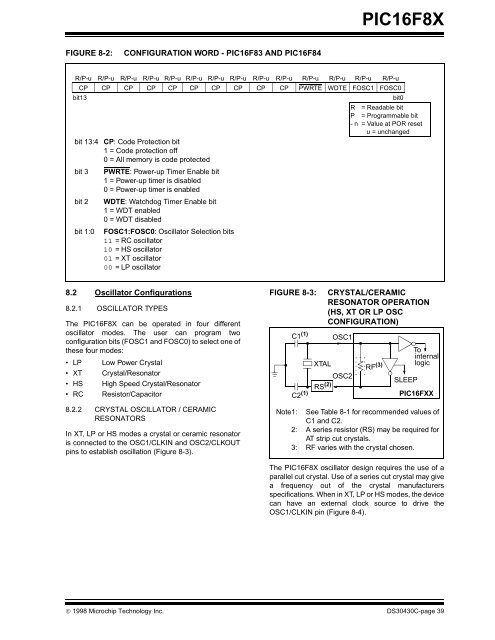
FIGURE 8-2: CONFIGURATION WORD - PIC16F83 AND PIC16F84<br />
8.2 Oscillator Configurations<br />
8.2.1 OSCILLATOR TYPES<br />
The <strong>PIC16F8X</strong> can be operated in four different<br />
oscillator modes. The user can program two<br />
configuration bits (FOSC1 and FOSC0) to select one of<br />
these four modes:<br />
• LP Low Power Crystal<br />
• XT Crystal/Resonator<br />
• HS High Speed Crystal/Resonator<br />
• RC Resistor/Capacitor<br />
8.2.2 CRYSTAL OSCILLATOR / CERAMIC<br />
RESONATORS<br />
In XT, LP or HS modes a crystal or ceramic resonator<br />
is connected to the OSC1/CLKIN and OSC2/CLKOUT<br />
pins to establish oscillation (Figure 8-3).<br />
<strong>PIC16F8X</strong><br />
R/P-u R/P-u R/P-u R/P-u R/P-u R/P-u R/P-u R/P-u R/P-u R/P-u R/P-u R/P-u R/P-u R/P-u<br />
CP CP CP CP CP CP CP CP CP CP PWRTE WDTE FOSC1 FOSC0<br />
bit13 bit0<br />
R = Readable bit<br />
P = Programmable bit<br />
- n = Value at POR reset<br />
u = unchanged<br />
bit 13:4 CP: Code Protection bit<br />
1 = Code protection off<br />
0 = All memory is code protected<br />
bit 3 PWRTE: Power-up Timer Enable bit<br />
1 = Power-up timer is disabled<br />
0 = Power-up timer is enabled<br />
bit 2 WDTE: Watchdog Timer Enable bit<br />
1 = WDT enabled<br />
0 = WDT disabled<br />
bit 1:0 FOSC1:FOSC0: Oscillator Selection bits<br />
11 = RC oscillator<br />
10 = HS oscillator<br />
01 = XT oscillator<br />
00 = LP oscillator<br />
FIGURE 8-3: CRYSTAL/CERAMIC<br />
RESONATOR OPERATION<br />
(HS, XT OR LP OSC<br />
CONFIGURATION)<br />
Note1: See Table 8-1 for recommended values of<br />
C1 and C2.<br />
2: A series resistor (RS) may be required for<br />
AT strip cut crystals.<br />
3: RF varies with the crystal chosen.<br />
The <strong>PIC16F8X</strong> oscillator design requires the use of a<br />
parallel cut crystal. Use of a series cut crystal may give<br />
a frequency out of the crystal manufacturers<br />
specifications. When in XT, LP or HS modes, the device<br />
can have an external clock source to drive the<br />
OSC1/CLKIN pin (Figure 8-4).<br />
© 1998 <strong>Microchip</strong> Technology Inc. DS30430C-page 39<br />
C1 (1)<br />
C2 (1)<br />
OSC1<br />
XTAL<br />
OSC2<br />
RS (2)<br />
RF (3)<br />
SLEEP<br />
To<br />
internal<br />
logic<br />
PIC16FXX


