

PIC16F8X, 18-Pin FLASH/EEPROM 8-Bit MCU Data Sheet - Microchip
PIC16F8X, 18-Pin FLASH/EEPROM 8-Bit MCU Data Sheet - Microchip
PIC16F8X, 18-Pin FLASH/EEPROM 8-Bit MCU Data Sheet - Microchip

You also want an ePaper? Increase the reach of your titles
YUMPU automatically turns print PDFs into web optimized ePapers that Google loves.
<strong>PIC16F8X</strong><br />
8.12 Power-down Mode (SLEEP)<br />
A device may be powered down (SLEEP) and later<br />
powered up (Wake-up from SLEEP).<br />
8.12.1 SLEEP<br />
The Power-down mode is entered by executing the<br />
SLEEP instruction.<br />
If enabled, the Watchdog Timer is cleared (but keeps<br />
running), the PD bit (STATUS) is cleared, the TO bit<br />
(STATUS) is set, and the oscillator driver is turned<br />
off. The I/O ports maintain the status they had before<br />
the SLEEP instruction was executed (driving high, low,<br />
or hi-impedance).<br />
For the lowest current consumption in SLEEP mode,<br />
place all I/O pins at either at VDD or VSS, with no<br />
external circuitry drawing current from the I/O pins, and<br />
disable external clocks. I/O pins that are hi-impedance<br />
inputs should be pulled high or low externally to avoid<br />
switching currents caused by floating inputs. The<br />
T0CKI input should also be at VDD or VSS. The<br />
contribution from on-chip pull-ups on PORTB should be<br />
considered.<br />
The MCLR pin must be at a logic high level (VIHMC).<br />
It should be noted that a RESET generated by a WDT<br />
time-out does not drive the MCLR pin low.<br />
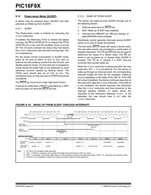
FIGURE 8-19: WAKE-UP FROM SLEEP THROUGH INTERRUPT<br />
OSC1<br />
CLKOUT(4)<br />
INT pin<br />
INTF flag<br />
(INTCON)<br />
GIE bit<br />
(INTCON)<br />
INSTRUCTION FLOW<br />
PC<br />
Instruction<br />
fetched<br />
Instruction<br />
executed<br />
8.12.2 WAKE-UP FROM SLEEP<br />
The device can wake-up from SLEEP through one of<br />
the following events:<br />
1. External reset input on MCLR pin.<br />
2. WDT Wake-up (if WDT was enabled).<br />
3. Interrupt from RB0/INT pin, RB port change, or<br />
data <strong>EEPROM</strong> write complete.<br />
Peripherals cannot generate interrupts during SLEEP,<br />
since no on-chip Q clocks are present.<br />
The first event (MCLR reset) will cause a device reset.<br />
The two latter events are considered a continuation of<br />
program execution. The TO and PD bits can be used to<br />
determine the cause of a device reset. The PD bit,<br />
which is set on power-up, is cleared when SLEEP is<br />
invoked. The TO bit is cleared if a WDT time-out<br />
occurred (and caused wake-up).<br />
While the SLEEP instruction is being executed, the next<br />
instruction (PC + 1) is pre-fetched. For the device to<br />
wake-up through an interrupt event, the corresponding<br />
interrupt enable bit must be set (enabled). Wake-up<br />
occurs regardless of the state of the GIE bit. If the GIE<br />
bit is clear (disabled), the device continues execution at<br />
the instruction after the SLEEP instruction. If the GIE bit<br />
is set (enabled), the device executes the instruction<br />
after the SLEEP instruction and then branches to the<br />
interrupt address (0004h). In cases where the<br />
execution of the instruction following SLEEP is not<br />
desirable, the user should have a NOP after the<br />
SLEEP instruction.<br />
Q1 Q2 Q3 Q4 Q1 Q2 Q3 Q4 Q1 Q1 Q2 Q3 Q4 Q1 Q2 Q3 Q4 Q1 Q2 Q3 Q4 Q1 Q2 Q3 Q4<br />
PC PC+1 PC+2<br />
Inst(PC) = SLEEP<br />
Inst(PC - 1)<br />
Inst(PC + 1)<br />
SLEEP<br />
Processor in<br />
SLEEP<br />
TOST(2)<br />
Inst(PC + 2)<br />
Inst(PC + 1)<br />
Interrupt Latency<br />
(Note 2)<br />
PC + 2 0004h 0005h<br />
Dummy cycle<br />
Inst(0004h) Inst(0005h)<br />
Dummy cycle<br />
Inst(0004h)<br />
Note 1: XT, HS or LP oscillator mode assumed.<br />
2: TOST = 1024TOSC (drawing not to scale) This delay will not be there for RC osc mode.<br />
3: GIE = ’1’ assumed. In this case after wake- up, the processor jumps to the interrupt routine. If GIE = ’0’, execution will continue in-line.<br />
4: CLKOUT is not available in these osc modes, but shown here for timing reference.<br />
DS30430C-page 52 © 1998 <strong>Microchip</strong> Technology Inc.<br />
PC+2


