

PIC16F8X, 18-Pin FLASH/EEPROM 8-Bit MCU Data Sheet - Microchip
PIC16F8X, 18-Pin FLASH/EEPROM 8-Bit MCU Data Sheet - Microchip
PIC16F8X, 18-Pin FLASH/EEPROM 8-Bit MCU Data Sheet - Microchip

Create successful ePaper yourself
Turn your PDF publications into a flip-book with our unique Google optimized e-Paper software.
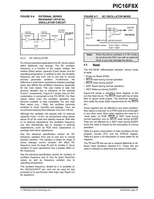
FIGURE 8-6: EXTERNAL SERIES<br />
RESONANT CRYSTAL<br />
OSCILLATOR CIRCUIT<br />
330 kΩ<br />
74AS04<br />
0.1 μF<br />
XTAL<br />
330 kΩ<br />
8.2.4 RC OSCILLATOR<br />
74AS04 74AS04<br />
To Other<br />
Devices<br />
PIC16FXX<br />
CLKIN<br />
For timing insensitive applications the RC device option<br />
offers additional cost savings. The RC oscillator<br />
frequency is a function of the supply voltage, the<br />
resistor (Rext) values, capacitor (Cext) values, and the<br />
operating temperature. In addition to this, the oscillator<br />
frequency will vary from unit to unit due to normal<br />
process parameter variation. Furthermore, the<br />
difference in lead frame capacitance between package<br />
types also affects the oscillation frequency, especially<br />
for low Cext values. The user needs to take into<br />
account variation due to tolerance of the external<br />
R and C components. Figure 8-7 shows how an R/C<br />
combination is connected to the <strong>PIC16F8X</strong>. For Rext<br />
values below 4 kΩ, the oscillator operation may<br />
become unstable, or stop completely. For very high<br />
Rext values (e.g., 1 MΩ), the oscillator becomes<br />
sensitive to noise, humidity and leakage. Thus, we<br />
recommend keeping Rext between 5 kΩ and 100 kΩ.<br />
Although the oscillator will operate with no external<br />
capacitor (Cext = 0 pF), we recommend using values<br />
above 20 pF for noise and stability reasons. With little<br />
or no external capacitance, the oscillation frequency<br />
can vary dramatically due to changes in external<br />
capacitances, such as PCB trace capacitance or<br />
package lead frame capacitance.<br />
See the electrical specification section for RC<br />
frequency variation from part to part due to normal<br />
process variation. The variation is larger for larger R<br />
(since leakage current variation will affect RC<br />
frequency more for large R) and for smaller C (since<br />
variation of input capacitance has a greater affect on<br />
RC frequency).<br />
See the electrical specification section for variation of<br />
oscillator frequency due to VDD for given Rext/Cext<br />
values as well as frequency variation due to<br />
operating temperature.<br />
The oscillator frequency, divided by 4, is available on<br />
the OSC2/CLKOUT pin, and can be used for test<br />
purposes or to synchronize other logic (see Figure 3-2<br />
for waveform).<br />
<strong>PIC16F8X</strong><br />
FIGURE 8-7: RC OSCILLATOR MODE<br />
Note: When the device oscillator is in RC mode,<br />
do not drive the OSC1 pin with an external<br />
clock or you may damage the device.<br />
8.3 Reset<br />
The <strong>PIC16F8X</strong> differentiates between various kinds<br />
of reset:<br />
• Power-on Reset (POR)<br />
• MCLR reset during normal operation<br />
• MCLR reset during SLEEP<br />
• WDT Reset (during normal operation)<br />
• WDT Wake-up (during SLEEP)<br />
Figure 8-8 shows a simplified block diagram of the<br />
on-chip reset circuit. The MCLR reset path has a noise<br />
filter to ignore small pulses. The electrical specifications<br />
state the pulse width requirements for the MCLR<br />
pin.<br />
Some registers are not affected in any reset condition;<br />
their status is unknown on a POR reset and unchanged<br />
in any other reset. Most other registers are reset to a<br />
“reset state” on POR, MCLR or WDT reset during<br />
normal operation and on MCLR reset during SLEEP.<br />
They are not affected by a WDT reset during SLEEP,<br />
since this reset is viewed as the resumption of normal<br />
operation.<br />
Table 8-3 gives a description of reset conditions for the<br />
program counter (PC) and the STATUS register.<br />
Table 8-4 gives a full description of reset states for all<br />
registers.<br />
The TO and PD bits are set or cleared differently in different<br />
reset situations (Section 8.7). These bits are<br />
used in software to determine the nature of the reset.<br />
© 1998 <strong>Microchip</strong> Technology Inc. DS30430C-page 41<br />
Rext<br />
Cext<br />
VDD<br />
OSC1<br />
VSS<br />
OSC2/CLKOUT<br />
Fosc/4<br />
Recommended values: 5 kΩ ≤ Rext ≤ 100 kΩ<br />
Cext > 20pF<br />
Internal<br />
clock<br />
PIC16FXX


