

PIC16F8X, 18-Pin FLASH/EEPROM 8-Bit MCU Data Sheet - Microchip
PIC16F8X, 18-Pin FLASH/EEPROM 8-Bit MCU Data Sheet - Microchip
PIC16F8X, 18-Pin FLASH/EEPROM 8-Bit MCU Data Sheet - Microchip

Create successful ePaper yourself
Turn your PDF publications into a flip-book with our unique Google optimized e-Paper software.
<strong>PIC16F8X</strong><br />
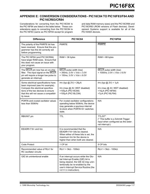
APPENDIX E: CONVERSION CONSIDERATIONS - PIC16C84 TO PIC16F83/F84 AND<br />
PIC16CR83/CR84<br />
Considerations for converting from the PIC16C84 to<br />
the PIC16F84 are listed in the table below. These considerations<br />
apply to converting from the PIC16C84 to<br />
the PIC16F83 (same as PIC16F84 except for program<br />
and data RAM memory sizes) and the PIC16CR84 and<br />
PIC16CR83 (ROM versions of Flash devices). Development<br />
Systems support is available for all of the<br />
PIC16X8X devices.<br />
Difference PIC16C84 PIC16F84<br />
The polarity of the PWRTE bit has<br />
been reversed. Ensure that the programmer<br />
has this bit correctly set<br />
before programming.<br />
The PIC16F84 (and PIC16CR84)<br />
have larger RAM sizes. Ensure that<br />
this does not cause an issue with<br />
your program.<br />
The MCLR pin now has an on-chip<br />
filter. The input signal on the MCLR<br />
pin will require a longer low pulse to<br />
generate an interrupt.<br />
Some electrical specifications have<br />
been improved (see IPD example).<br />
Compare the electrical specifications<br />
of the two devices to ensure<br />
that this will not cause a compatibility<br />
issue.<br />
PORTA and crystal oscillator values<br />
less than 500kHz<br />
PWRTE PWRTE<br />
RAM = 36 bytes RAM = 68 bytes<br />
MCLR pulse width (low)<br />
= 350ns; 2.0V ≤ VDD ≤ 3.0V<br />
= 150ns; 3.0V ≤ VDD ≤ 6.0V<br />
IPD (typ @ 2V) = 26μA<br />
IPD (max @ 4V, WDT disabled)<br />
=100μA (PIC16C84)<br />
=100μA (PIC16LC84)<br />
For crystal oscillator configurations<br />
operating below 500kHz, the device<br />
may generate a spurious internal<br />
Q-clock when PORTA switches<br />
state.<br />
MCLR pulse width (low)<br />
= 1000ns; 2.0V ≤ VDD ≤ 6.0V<br />
IPD (typ @ 2V) < 1μA<br />
IPD (max @ 4V, WDT disabled)<br />
=14μA (PIC16F84)<br />
=7μA (PIC16LF84)<br />
RB0/INT pin TTL TTL/ST*<br />
(* This buffer is a Schmitt Trigger<br />
input when configured as the external<br />
interrupt.)<br />
EEADR and IDD It is recommended that the<br />
EEADR bits be cleared.<br />
When either of these bits is set, the<br />
maximum IDD for the device is<br />
higher than when both are cleared.<br />
Code Protect 1 CP bit 9 CP bits<br />
Recommended value of REXT for<br />
RC oscillator circuits<br />
© 1998 <strong>Microchip</strong> Technology Inc. DS30430C-page 117<br />
N/A<br />
N/A<br />
REXT = 3kΩ - 100kΩ REXT = 5kΩ - 100kΩ<br />
GIE bit unintentional enable If an interrupt occurs while the Global<br />
Interrupt Enable (GIE) bit is<br />
being cleared, the GIE bit may unintentionally<br />
be re-enabled by the<br />
user’s Interrupt Service Routine (the<br />
RETFIE instruction).<br />
N/A


