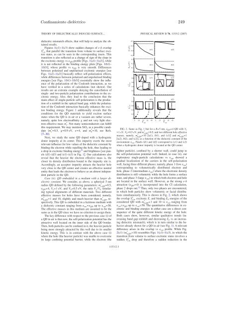
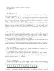
248 PublicacionesRAJADELL et al.fundamental 1S e electron and 1S 3/2 hole states. Then, thehole in the fundamental exciton has a strong heavy-holecharacter, being well described by the one-band model. Themissing small contribution of the light holes in the excitonconfiguration interaction CI expansion is expected to benegligible. This simplification on the hole description leadsto a computational workable approach. Also, the electronholespin-exchange interaction that splits the optically activeexciton ground state into a few states, 2,18,19 the lowest ofwhich is optically passive, has been neglected in the presentstudy. Then, to account for excitonic states, we first solve theone-particle effective-mass Schrödinger equation,H =− 1 2 1m * r + Vr + V sr,where the first term is the generalized kinetic energy operator,Vr represents the spatial confining potential, and V s rstands for the self-polarization potential. The calculation ofthis potential is carried out by employing a dielectric functionprofile that changes smoothly within a thin interface ofthe order of a lattice constant between the semiconductorQD and its surroundings. 10,20 This approach bypasses theunphysical self-polarization potential divergences that ariseat the interface when a steplike dielectric profile isemployed 17,21 and avoids the lack of size scaling of the nondivergentregularization method. 11,17The radial parts of the exact single-particle eigenfunctions nm r e/h are determined numerically on the grid extendingfar beyond the dot radius R. Hartree products of the basisfunctions nm r e · n m r h are then used to construct CIexpansions LM = j j of the symmetry-adapted e-h configurations,where L and M are the total and z-componentangular quantum numbers, respectively. The e-h Hamiltoniancontaining Coulomb interaction and polarization terms 10 isthen diagonalized in the CI basis set. As a result, we gettwo-particle wave functions LM r e ,r h and energies EL.We carry out full CI employing a very large orbital basis set nm including the n=4 lowest-lying orbitals with =0,1,2and the n=3 lowest-lying orbitals with =3,4,5,6. Thesame basis set is employed for electron and holes, this basisset being by far larger than that required to achieve the accuracyshown in the figures.From the wave function, we can define the electron radialdensity Pr e ,Pr e = r e ,r h 2 r e 2 r h 2 sin e sin h dr h d e d h d e d h ,the hole radial density Pr h in a similar way, and the e-hoverlap S 2 e-h ,2S e-h = r e = r h = rr 2 sin drdd2, 3which is proportional to the oscillator strength of theelectron-hole state. 16,22–2412E (eV)E (eV)S2 2 e−hE (eV)S e−h0.50−0.5−1−1.5−221.510.5010.80.60.40.2021.510.50−0.510.80.60.40.2III. RESULTS AND DISCUSSIONCase (i): QD in air or a vacuum. We first investigate therole of image charges on the excitonic properties of a freestandingQD. Our model consists of a spherical R=5 nmradius nanocrystal. We employ the following parameters: 25*m e,QD**=m h,out=0.5, m e,out =1, m h,QD =10, and out =1. Sincewe cannot promote holes into a vacuum, we will assume aninfinite height for the spatial confining barrier of a hole whena QD is in air or a vacuum. As for electrons, we consider theQD electroaffinity as the barrier height V e .We have carried out three series of calculations of the2(a1)(b1)(c1)(d1)(e1)PHYSICAL REVIEW B 76, 115312 2007overlap S e-h and excitonic E and binding E b energies 26 vs QD ranging from 1 up to 50, corresponding to V e =1,2,and3 eV. The results are summarized in Fig. 1, together withpartner calculations with out = QD , i.e., in the absence of*(a2)(b2)(c2)(d2)(e2)05 15 25 35 45 5 15 25 35 45ε QDεQD(a3)(b3)(c3)(d3)(e3)5 15 25 35 45ε QDFIG. 1. Excitonic E and binding E b energies and e-h overlap2**S e-h of a R=5 nm, m e,QD =0.5, m h,QD =10 freestanding QD with aconfining barrier height V e of 1 eV a1, b1, and c1, 2eVa2, b2, c2, and 3 eV c1, c2, c3, as a function of theQD dielectric constant QD . Solid dashed lines include excludedielectric polarization effects. Insets: electron solid line and holedotted line radial density distributions Eq. 2 the QD border isindicated by a tick in the horizontal axis. Panels d1–d3 ande1–e3 correspond to b1–b3 and c1–c3 when a hydrogenicdonor impurity is located at the QD center.115312-2
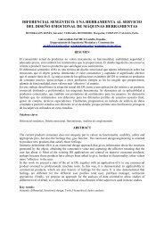
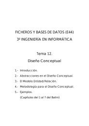
Confinamiento dieléctrico 249THEORY OF DIELECTRICALLY INDUCED SURFACE…dielectric mismatch effects, that will help to analyze the obtainedresults.Figures 1c1–1c3 show sudden changes of e-h overlap2S e-hthat parallel the transition from volume to surface excitonstates, as can be seen in the corresponding insets. Thistransition is also reflected as a change of sign of the slope inthe excitonic energy vs QD profile Figs. 1a1–1a3, whileit is not reflected in the binding energy plots Figs. 1b1–1b3, whose profile vs QD is very smooth. Differencesbetween polarized and unpolarized excitonic energies seeFigs. 1a1–1a3 basically reflect self-polarization effects,while differences between polarized and unpolarized bindingenergies see Figs. 1b1–1b3 essentially show the influenceof the polarization of the Coulomb interaction, as wehave verified in a series of calculations not shown. Ourresults are an extreme example denying the cancellation ofsingle- and two-particle polarization contributions to the excitonicenergy. Also, they lead to the conclusion that themain effect of single-particle self-polarization is the productionof a redshift in the optical band gap, while the polarizationof the Coulomb interaction basically enhances the excitonbinding energy. Figure 1 additionally reveals that theconditions for the QD materials to yield exciton surfacestates when the QD is in air or a vacuum are rather severe,namely, quite low electroaffinity and not very light electroneffective mass m * e . Not many semiconductors can fulfillthis requirement. We may mention SiO 2 as a possible candidatem * e =0.5, =0.9 eV, =4, and m * h =10, see Refs.27–30.Next, we study the same QD doped with a hydrogenicdonor impurity at its center. This impurity exerts the mostrelevant influence for low values of the dielectric constant bybinding the electron while repelling the hole, thus leading toa drop in excitonic binding energy 31 and brightness see panelsd1–d3 and e1–e3 in Fig. 1. Our calculations alsoreveal that the heavier the electron effective mass is, thecloser its density distribution bound to the impurity site is.Accordingly, an acceptor impurity attracts the heavier holevery close to the QD center and creates an effective neutralentity that leads the electron to behave as an almost independentparticle in the QD.Case (ii): QD embedded in a medium with a larger dielectricconstant. We consider, as above, a spherical 5 nmradius QD defined by the following parameters: m e,QD =0.5, QD =4, V e =1 eV, and V h =0.5 eV, the ratio V e /V h simulatingtypical alignments of different materials. Two differenteffective masses for holes have been considered, namely,*m h,QD=1 and 10, slightly and much heavier than m e,QD , respectively.This QD is embedded in a fictitious medium witha dielectric constant ranging from out = QD up to out =50.The effective masses in this medium are assumed to be thesame as in the QD since we have no criterion to assign them.The key difference with respect to the previous case i ofa QD in air is that now, the self-polarization potential has theattractive well located on the inner side of the QD border.Then, both particles can be confined in it, the heavier particlebeing more strongly attracted by this well due to its smallerkinetic energy. This is in contrast with the above case iwhere the hole the heavier particle was unable to overcomeits large confining potential barrier, while the electron the**E (eV)E (eV)2e−hSS 2 e−h−0.2−0.4−0.6−0.80.30.20.1010.80.60.40.2010.80.60.40.20515PHYSICAL REVIEW B 76, 115312 2007(a1)(b1)(c1)(d1)25 35 45 5 15 25 35 45ε outε outFIG. 2. Same as Fig. 1 but for a R=5 nm, QD =4 QD with V e*=1 eV, V h =0.5 eV, and m e,QD =0.5, and two different hole effective**masses, namely, m h,QD =10 a1, b1, and c1 and m h,QD =1a2, b2, and c2, as a function of the dielectric constant of theenvironment out . Panels d1 and d2 correspond to c1 and c2when a hydrogenic donor impurity is located at the QD center.lighter particle, confined by a shorter wall, could jump tothe self-polarization potential well. Indeed, in case ii, ourexploratory single-particle calculations vs out showed agradual localization of the carriers in the self-polarizationwell, facing three different phases: namely, phase 1 low out corresponding to volumetrically distributed electron andhole, phase 2 intermediate out where the electronic densitydistribution is still volumetric while the hole forms a surfacestate, and phase 3 large out in which both electron and holeare located in the surface well. However, as the strong e-hattraction QD =4 is incorporated into the CI calculation,phase 2 drops out. 32 Thus, only two phases are encountered,in which both particles show volumetric or facial distributionssimultaneously. This is shown in Fig. 2, which showsthe overlap S 2 e-h , excitonic E, and binding E b energies of the*considered QD with m h,QD =1 and 10 vs out ranging from out = QD up to out =50. The quantitative differences in excitonicand binding energies in either case are a direct consequenceof the quite different kinetic energy of the hole.Both cases show, however, similar qualitative trends increasingband gap redshift and decreasing E b vs an increasingdielectric mismatch, which is in turn similar to the behavioralready shown for a QD in air see Fig. 1. A relevantdifference arises in the overlap vs out profile. While Fig.*2c1 m h,QD =10 resembles Figs. 1c1–1c3, in which thetransition from volume to surface excitonic states involves a2sudden S e-h drop and therefore a sudden reduction in the(a2)(b2)(c2)(d2)115312-3
- Page 1:
CONFINAMIENTO NANOSCÓPICO ENESTRUC
- Page 5 and 6:
AgradecimientosDecía Albert Einste
- Page 7:
A mi madreA la memoria de mi padre
- Page 10 and 11:
viiihigh-correlation electronic reg
- Page 12 and 13:
xric) resolution method proves the
- Page 14 and 15:
xii14. F. Rajadell, J.L. Movilla, M
- Page 16 and 17:
xivcen para moldear a voluntad su e
- Page 18 and 19:
xvideterminar las características
- Page 23 and 24:
Capítulo 1Fundamentos teóricosEl
- Page 25 and 26:
1.1 Modelo k · p 3donde p = −i¯
- Page 27 and 28:
1.1 Modelo k · p 5inversa de la ma
- Page 29 and 30:
1.2 Heteroestructuras. Aproximació
- Page 31 and 32:
1.3 Masa efectiva dependiente de la
- Page 33 and 34:
1.4 Aplicación de un campo magnét
- Page 35 and 36:
1.5 Potenciales monopartícula adic
- Page 37 and 38:
1.6 Integración numérica del hami
- Page 39 and 40:
1.7 Transiciones intrabanda 17Tras
- Page 41 and 42:
1.7 Transiciones intrabanda 19g) [7
- Page 43 and 44:
Capítulo 2Confinamientos espacial
- Page 45 and 46:
23esta aproximación asume implíci
- Page 47 and 48:
2.1 Puntos cuánticos de InAs en ma
- Page 49 and 50:
2.1 Puntos cuánticos de InAs en ma
- Page 51 and 52:
2.1 Puntos cuánticos de InAs en ma
- Page 53 and 54:
2.1 Puntos cuánticos de InAs en ma
- Page 55 and 56:
Capítulo 3Confinamiento periódico
- Page 57 and 58:
3.1 Funciones de Wannier 35otro con
- Page 59 and 60:
3.1 Funciones de Wannier 373.1.1. F
- Page 61 and 62:
3.2 Evolución temporal en modelos
- Page 63 and 64:
3.2 Evolución temporal en modelos
- Page 65 and 66:
3.2 Evolución temporal en modelos
- Page 67 and 68:
3.3 Tiempo de tunneling en cadenas
- Page 69 and 70:
3.3 Tiempo de tunneling en cadenas
- Page 71 and 72:
Capítulo 4Confinamiento magnético
- Page 73 and 74:
51donde m ∗ es la masa efectiva d
- Page 75 and 76:
4.1 Magnetización de puntos y anil
- Page 77 and 78:
4.1 Magnetización de puntos y anil
- Page 79 and 80:
4.1 Magnetización de puntos y anil
- Page 81 and 82:
4.2 Acoplamiento lateral de anillos
- Page 83 and 84:
4.2 Acoplamiento lateral de anillos
- Page 85 and 86:
4.2 Acoplamiento lateral de anillos
- Page 87 and 88:
4.2 Acoplamiento lateral de anillos
- Page 89 and 90:
Capítulo 5Confinamiento dieléctri
- Page 91 and 92:
69Más complicado pero también ana
- Page 93 and 94:
5.1 Validez de la electrodinámica
- Page 95 and 96:
5.2 Interacciones culómbicas en pu
- Page 97 and 98:
5.2 Interacciones culómbicas en pu
- Page 99 and 100:
5.3 Barreras confinantes finitas e
- Page 101 and 102:
5.3 Barreras confinantes finitas e
- Page 103 and 104:
5.3 Barreras confinantes finitas e
- Page 105 and 106:
5.3 Barreras confinantes finitas e
- Page 107 and 108:
5.4 Impurezas dadoras hidrogenoides
- Page 109 and 110:
5.4 Impurezas dadoras hidrogenoides
- Page 111 and 112:
5.4 Impurezas dadoras hidrogenoides
- Page 113 and 114:
5.4 Impurezas dadoras hidrogenoides
- Page 115 and 116:
5.4 Impurezas dadoras hidrogenoides
- Page 117 and 118:
5.4 Impurezas dadoras hidrogenoides
- Page 119 and 120:
5.4 Impurezas dadoras hidrogenoides
- Page 121 and 122:
5.4 Impurezas dadoras hidrogenoides
- Page 123 and 124:
5.4 Impurezas dadoras hidrogenoides
- Page 125 and 126:
5.4 Impurezas dadoras hidrogenoides
- Page 127 and 128:
5.4 Impurezas dadoras hidrogenoides
- Page 129 and 130:
5.5 Estados superficiales inducidos
- Page 131 and 132:
5.5 Estados superficiales inducidos
- Page 133 and 134:
5.5 Estados superficiales inducidos
- Page 135 and 136:
5.5 Estados superficiales inducidos
- Page 137 and 138:
5.5 Estados superficiales inducidos
- Page 139 and 140:
5.5 Estados superficiales inducidos
- Page 141 and 142:
5.5 Estados superficiales inducidos
- Page 143 and 144:
5.5 Estados superficiales inducidos
- Page 145 and 146:
5.5 Estados superficiales inducidos
- Page 147 and 148:
5.5 Estados superficiales inducidos
- Page 149 and 150:
5.5 Estados superficiales inducidos
- Page 151 and 152:
5.5 Estados superficiales inducidos
- Page 153 and 154:
5.5 Estados superficiales inducidos
- Page 155 and 156:
5.5 Estados superficiales inducidos
- Page 157 and 158:
5.5 Estados superficiales inducidos
- Page 159 and 160:
5.5 Estados superficiales inducidos
- Page 161 and 162:
5.5 Estados superficiales inducidos
- Page 163 and 164:
5.5 Estados superficiales inducidos
- Page 165 and 166:
5.5 Estados superficiales inducidos
- Page 167 and 168:
5.5 Estados superficiales inducidos
- Page 169 and 170:
5.5 Estados superficiales inducidos
- Page 171 and 172:
5.5 Estados superficiales inducidos
- Page 173 and 174:
5.5 Estados superficiales inducidos
- Page 175 and 176:
Capítulo 6ConclusionesEn esta Tesi
- Page 177 and 178:
155entre los anillos como la orient
- Page 179 and 180:
157fuerte decaimiento de la intensi
- Page 181 and 182:
Publicaciones
- Page 183 and 184:
Confinamientos espacial y másico
- Page 185 and 186:
Confinamientos espacial y másico 1
- Page 187 and 188:
Confinamientos espacial y másico 1
- Page 189 and 190:
Confinamientos espacial y másico 1
- Page 191 and 192:
Confinamiento periódico
- Page 193 and 194:
Confinamiento periódico 171J. Phys
- Page 195 and 196:
Confinamiento periódico 173Tunneli
- Page 197 and 198:
Confinamiento periódico 175Tunneli
- Page 199 and 200:
Confinamiento magnético
- Page 201 and 202:
Confinamiento magnético 179Symmetr
- Page 203 and 204:
Confinamiento magnético 181Aharono
- Page 205 and 206:
Confinamiento magnético 183Aharono
- Page 207 and 208:
Confinamiento magnético 185Aharono
- Page 209 and 210:
Confinamiento magnético 187PHYSICA
- Page 211 and 212:
Confinamiento magnético 189MAGNETI
- Page 213 and 214:
Confinamiento magnético 191IOP Pub
- Page 215 and 216:
Confinamiento magnético 193938Mean
- Page 217 and 218:
Confinamiento magnético 195940QRs
- Page 219 and 220: Confinamiento dieléctrico
- Page 221 and 222: Confinamiento dieléctrico 199Compu
- Page 223 and 224: Confinamiento dieléctrico 201146 J
- Page 225 and 226: Confinamiento dieléctrico 203148 J
- Page 227 and 228: Confinamiento dieléctrico 205150 J
- Page 229 and 230: Confinamiento dieléctrico 207152 J
- Page 231 and 232: Confinamiento dieléctrico 209PHYSI
- Page 233 and 234: Confinamiento dieléctrico 211OFF-C
- Page 235 and 236: Confinamiento dieléctrico 213OFF-C
- Page 237 and 238: Confinamiento dieléctrico 215OFF-C
- Page 239 and 240: Confinamiento dieléctrico 217PHYSI
- Page 241 and 242: Confinamiento dieléctrico 219BRIEF
- Page 243 and 244: Confinamiento dieléctrico 221PHYSI
- Page 245 and 246: Confinamiento dieléctrico 223TRAPP
- Page 247 and 248: Confinamiento dieléctrico 225Deloc
- Page 249 and 250: Confinamiento dieléctrico 227V s (
- Page 251 and 252: Confinamiento dieléctrico 229with
- Page 253 and 254: Confinamiento dieléctrico 231value
- Page 255 and 256: Confinamiento dieléctrico 233(R in
- Page 257 and 258: Confinamiento dieléctrico 23525R i
- Page 259 and 260: Confinamiento dieléctrico 237monoe
- Page 261 and 262: Confinamiento dieléctrico 239[8] Y
- Page 263 and 264: Confinamiento dieléctrico 241[48]
- Page 265 and 266: Confinamiento dieléctrico 243PHYSI
- Page 267 and 268: Confinamiento dieléctrico 245FROM
- Page 269: Confinamiento dieléctrico 247PHYSI
- Page 273 and 274: Confinamiento dieléctrico 251THEOR
- Page 275 and 276: Confinamiento dieléctrico 253PHYSI
- Page 277 and 278: Confinamiento dieléctrico 255DIELE
- Page 279 and 280: Confinamiento dieléctrico 257DIELE
- Page 281 and 282: Confinamiento dieléctrico 259DIELE
- Page 283 and 284: Confinamiento dieléctrico 261DIELE
- Page 285 and 286: Confinamiento dieléctrico 263PHYSI
- Page 287 and 288: Confinamiento dieléctrico 265FAR-I
- Page 289 and 290: Confinamiento dieléctrico 267FAR-I
- Page 291 and 292: Confinamiento dieléctrico 269Diele
- Page 293 and 294: Confinamiento dieléctrico 271Diele
- Page 295 and 296: Confinamiento dieléctrico 273Diele
- Page 297 and 298: Confinamiento dieléctrico 275Diele
- Page 299 and 300: Confinamiento dieléctrico 277Diele
- Page 301 and 302: Confinamiento dieléctrico 279Diele
- Page 303 and 304: Confinamiento dieléctrico 281Diele
- Page 305 and 306: Confinamiento dieléctrico 283Diele
- Page 307 and 308: Confinamiento dieléctrico 285Diele
- Page 309 and 310: Confinamiento dieléctrico 287Diele
- Page 311 and 312: Confinamiento dieléctrico 289Diele
- Page 313 and 314: Confinamiento dieléctrico 291Diele
- Page 315 and 316: Bibliografía[1] J. Karwowski,“In
- Page 317 and 318: BIBLIOGRAFÍA 295[23] J.L. Movilla,
- Page 319 and 320: BIBLIOGRAFÍA 297[48] M.G. Burt,
- Page 321 and 322:
BIBLIOGRAFÍA 299[71] W.H. Press, S
- Page 323 and 324:
BIBLIOGRAFÍA 301[97] U.H. Lee, D.
- Page 325 and 326:
BIBLIOGRAFÍA 303[121] S.W. Chung,
- Page 327 and 328:
BIBLIOGRAFÍA 305[145] R. Blossey y
- Page 329 and 330:
BIBLIOGRAFÍA 307[169] F. Suárez,
- Page 331 and 332:
BIBLIOGRAFÍA 309[194] C. Delerue,
- Page 333 and 334:
BIBLIOGRAFÍA 311[220] J.L. Zhu y X
- Page 335 and 336:
BIBLIOGRAFÍA 313[245] L.M. Peter,
- Page 337 and 338:
BIBLIOGRAFÍA 315[266] P. Rinke, K.
- Page 339 and 340:
BIBLIOGRAFÍA 317[289] Y. Wang, L.
- Page 341 and 342:
BIBLIOGRAFÍA 319[314] A. Wójs y P