Contents - Max-Planck-Institut für Physik komplexer Systeme
Contents - Max-Planck-Institut für Physik komplexer Systeme
Contents - Max-Planck-Institut für Physik komplexer Systeme

You also want an ePaper? Increase the reach of your titles
YUMPU automatically turns print PDFs into web optimized ePapers that Google loves.
2.23 Measuring the Complete Force Field of an Optical Trap<br />
MARCUS JAHNEL, MARTIN BEHRNDT, ANITA JANNASCH, ERIK SCHÄFFER,<br />
STEPHAN W. GRILL<br />
Optical traps are widely used to investigate forces and<br />
displacements encountered on the molecular level, for<br />
example in the movement of molecular motors. To<br />
measure or apply forces in such studies requires the<br />
precise knowledge of the trapping force field, which<br />
is typically approximated as linear in the displacement<br />
of the trapped microsphere. Close to the trap center<br />
this linear assumption is valid and successfully used to<br />
set the scale of the measured forces and displacements<br />
when performing a thermal calibration. Here, thermal<br />
fluctuations of the microsphere around the center<br />
of the optical trap are measured and compared<br />
with theories of Brownian fluctuations in a confining<br />
harmonic potential [1, 2]. However, as this assumed<br />
linear force-displacement relation breaks down<br />
at larger microsphere displacements, applications demanding<br />
high forces at low laser intensities can probe<br />
the light-microsphere interaction beyond the linear<br />
regime. Thus, an exact mapping of the complete optical<br />
force field is not only necessary to determine the validity<br />
of the linear approximation, but enables the use of<br />
the full force range of an optical trap.<br />
Here, we measured the full non-linear force and displacement<br />
response of an optical trap in two dimensions<br />
[3]. We used a dual-beam optical trap setup<br />
with back-focal-plane photodetection [4] that allowed<br />
for independent adjustment of the positions and intensities<br />
of two optical traps [5]. A strong, thermallycalibrated<br />
trap [1], TC, in its linear operating regime<br />
acted as a precise sensor of force (and position) for<br />
analyzing a weaker, uncalibrated trap of interest, TA.<br />
While keeping TC stationary, we scanned TA in 10nm<br />
steps over the whole microsphere-interaction regime.<br />
At each step—with stationary traps and measurement<br />
times long enough to average over thermal<br />
fluctuations—the balance of the optical forces yields<br />
〈FC(r)〉tav = −〈FA(r)〉tav . To ensure the validity of the<br />
linear force-displacement approximation for the calibration<br />
trap to within 5 % (see below), we adjusted<br />
the relative intensities in both traps such that TC had<br />
at least a five times higher trap stiffness than TA. This<br />
then allows for measuring the full force-displacement<br />
relation of TA. Under the above conditions, we have<br />
ˆκC〈r − d〉tav = 〈FA(r)〉tav , (1)<br />
where the diagonal matrix ˆκC contains the trap stiffness<br />
of TC in the x- and y-direction. The distance<br />
vector between the two traps is denoted by d and is<br />
changed by scanning TA. Allowing the microsphere<br />
to relax to its new equilibrium position, we sampled<br />
the complete optical force profile for arbitrary displacement<br />
r relative to the center of TA. We determined a<br />
two-dimensional map of the optical forces exerted by<br />
TA on a polystyrene microsphere of diameter 1.26µm<br />
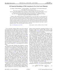
[Fig. 1(a)]. The net force, obtained by combining the<br />
parallel (Fx) and perpendicular (Fy) force components<br />
relative to the trap polarization, demonstrates that for<br />
this microsphere size the optical forces are nearly radially<br />
symmetric [Fig. 1(b)]. We therefore restrict our<br />
remaining discussion to cross-sections of the force map<br />
in x [dashed line in Fig. 1(c)]. Fitting the experimental<br />
data using numerical calculations based on the Tmatrix<br />
method [6] showed excellent agreement of our<br />
measurements with Mie scattering theory [Fig. 1(c)].<br />
Close to the origin, a constant trap stiffness—assuming<br />
Hooke’s law—is expected. However, numerical differentiation<br />
of the measured force curve shows that the<br />
trap stiffness continuously deviated from its value at<br />
the origin, κ0 = 72 ± 3 pN/µm [Fig. 1(d)]. Displacing<br />
the microsphere from the center, the trap stiffness<br />
increased moderately within the first 300 nm towards<br />
a maximum, before it fell off, and eventually became<br />
negative. In this region, the analogy between optical<br />
traps and mechanical springs fails; the trap stiffness is<br />
negative for a decreasing, yet, still restoring force.<br />
Displacement y (nm)<br />
−1000 0 1000<br />
−1000 0 1000<br />
(a) (c) Data<br />
Theory<br />
Force Fx (pN)<br />
(b) Polarization<br />
Radial force (pN)<br />
−1000 0 1000<br />
Displacement x (nm)<br />
5 10 15 20 25 30 35 −30 −15 0 15 30<br />
Force Fx (pN)<br />
Stiffness (pN/ µ m)<br />
20<br />
0<br />
−20<br />
100<br />
−100 0<br />
∅ = 1.26µ m<br />
(d)<br />
−1000 0 1000<br />
Displacement x (nm)<br />
Figure 1: 2D maps of (a) optical forces on a 1.26 µm microsphere<br />
in the direction of<br />
q<br />
polarization and of (b) the magnitude of the radial<br />
force |F | = F2 x + F2 y . Force magnitudes are color-coded by<br />
corresponding heat maps. (c) Complete force response along the<br />
polarization axis [dashed line in (a)]. (d) Numerical differentiation,<br />
κ(x) = − ∂x F(r), yielded the trap stiffness with respect to the microsphere<br />
displacement.<br />
86 Selection of Research Results