Contents - Max-Planck-Institut für Physik komplexer Systeme
Contents - Max-Planck-Institut für Physik komplexer Systeme
Contents - Max-Planck-Institut für Physik komplexer Systeme

Create successful ePaper yourself
Turn your PDF publications into a flip-book with our unique Google optimized e-Paper software.
Note that the stiffening effect was substantial even for<br />
small displacements. A displacement from the trap<br />
center of 250 nm already lead to a deviation of the trap<br />
stiffness of more than 30 % as compared with its value<br />
at the origin, which would be probed by thermal calibration.<br />
Thus, without any preliminary assumptions<br />
about the trap of interest (TA), we measured its full<br />
force field and analyzed the validity of the linear forcedisplacement<br />
approximation.<br />
A distinct second linear regime of higher constant<br />
trap stiffness was recently reported for 2.01µm microspheres<br />
[7]. To study the microsphere size dependence<br />
of the observed stiffening effect in more detail,<br />
we use our setup to compare the 1.26µm microspheres<br />
with larger ones of diameters 2.01µm and 2.40µm in<br />
Fig. 2(a) and (b). Indeed, the stiffening was more pronounced<br />
for larger microspheres and depended sensitively<br />
on their exact size. Figure 2(b) shows that the<br />
measured stiffness landscapes are complex, displaying<br />
ripples, yet no extended linear regime. Importantly,<br />
these non-linear effects are well described by Mie theory<br />
calculations [6]. Therefore, our approach allows for<br />
a detailed investigation of these optical phenomena.<br />
Next, we used our assay to evaluate the accuracy of<br />
the back-focal-plane detection method [4]. This sensitive<br />
detection method infers both the displacement<br />
and force from a single differential voltage signal on<br />
a position-sensitive photodetector. For small displacements,<br />
both measures are well approximated as linear<br />
functions of the differential voltage signal. For<br />
larger displacements, we found that the linear forcedisplacement<br />
relation breaks down [Figs. 1(c) and 2(a)].<br />
Force (% of Fmax)<br />
Stiffness (% of κ0)<br />
100<br />
−100 −50 0 50<br />
−400 −200 0 200<br />
∅<br />
(µm) (pN)<br />
1.26 37<br />
2.01 35<br />
2.40 48<br />
Fmax<br />
κ0<br />
(pN/µm)<br />
72<br />
22<br />
30<br />
0<br />
−2000 −1000 1000<br />
(a)<br />
(b)<br />
2000<br />
Displacement x (nm)<br />
Force (pN)<br />
Residuals (% of max)<br />
−40 −20 0 20 40 −20 0 20<br />
∅ = 2.01µm<br />
Linear fit ±0.2 V<br />
∅ = 2.01µm<br />
(c)<br />
(d)<br />
−0.8 −0.4 0 0.4 0.8<br />
−1000 0 1000<br />
Displacement x (nm)<br />
Detector signal of TA (V)<br />
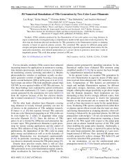
Figure 2: (a) Normalized force-extension curves and (b) thereof derived<br />
trap stiffnesses for indicated microsphere sizes. (c) Comparing<br />
forces (red) and displacements (green) to the detector signal of TA<br />
for a 2.01 µm microsphere. Shaded areas indicate where residuals<br />
[see (d)] of the linear fit are less than 5 % (dark) or less than 10 %<br />
(bright). (d) Force (red) and displacement (green) residuals of the fit<br />
in (c) normalized to F(Vmax) = 33 pN and x(Vmax) = 950 nm,<br />
respectively.<br />
However, it remains elusive to what extend each single<br />
quantity (force or displacement) can still be accurately<br />
described by a linear dependence of the detector signal.<br />
To address this, we correlated the calibrated force and<br />
displacement signals of the strong trap with the detector<br />
signal of the weak trap. As depicted in Fig. 2(c) and<br />
(d) for microspheres of diameter 2.01µm, assuming a<br />
linear relationship between force and voltage signal is<br />
correct to within ±5%, even for very large displacements<br />
close to the force maximum. On the other hand,<br />
inferring microsphere position from the same voltage<br />
signal—again assuming linearity—lead to significantly<br />
larger errors of up to 40 % [Fig. 2(d)].<br />
To conclude, an optical trap with back-focal-plane detection<br />
is foremost a sensor of force and not of position<br />
[4]. Positional information is inferred from a linear<br />
approximation of the optical force field, which does<br />
not hold for large microsphere displacements [Figs. 1(c)<br />
and 2(a)]. These findings have implications for detection<br />
methods that infer force from microsphere position,<br />
such as high-speed video microscopy [8]. Without<br />
a full characterization of the force field, accurate<br />
force measurements are in this case limited to the range<br />
where the linear force-displacement relation holds.<br />
In summary, we have shown how to measure the complete<br />
2D force field of an optical trap with a dual-beam<br />
optical trap setup. A strong calibration trap in its linear<br />
regime acts as an accurate force sensor. Our calibration<br />
strategy directly addresses the difficulties associated<br />
with inferring physical quantities from optical tweezers<br />
measurements that are based on the assumption<br />
of a linear trapping force field. The treatment of optical<br />
tweezers as springs is an approximation, valid<br />
only close to the trap center, and its validity depends<br />
sensitively on the size of the trapped object. By reporting<br />
a simple calibration scheme for absolute forces and<br />
displacements in an optical trap we provide a robust<br />
means for the study of the complete light-microsphereinteractions;<br />
for accurate tweezers measurements beyond<br />
the linear regime.<br />
[1] K. Berg-Sørensen and H. Flyvbjerg, Rev. Sci. Instrum. 75 (2004)<br />
594.<br />
[2] S. F. Tolić-Nørrelykke, E. Schäffer, J. Howard, F. S. Pavone,<br />
F. Jülicher, and H. Flyvbjerg, Rev. Sci. Instrum. 77 (2006) 3101.<br />
[3] M. Jahnel, M. Behrndt, A. Jannasch, E. Schäffer, S. W. Grill, Opt.<br />
Lett. 36 (2011) 1260.<br />
[4] F. Gittes and C. F. Schmidt, Opt. Lett. 23 (1998) 7.<br />
[5] C. Bustamante, Y. Chemla, and J. Moffitt, Single-Molecule Techniques:<br />
A Laboratory Manual (CSHL Press, 2008).<br />
[6] T. A. Nieminen, V. L. Y. Loke, A. B. Stilgoe, G. Knöner, A. M.<br />
Brańczyk, N. R. Heckenberg, and H. Rubinsztein-Dunlop, J.<br />
Opt. A: Pure Appl. Opt. 9, (2007) S196.<br />
[7] A. C. Richardson, S. N. S. Reihani, and L. B. Oddershede, Opt.<br />
Express 16 (2008) 15709.<br />
[8] G. M. Gibson, J. Leach, S. Keen, A. J. Wright, and M. J. Padgett,<br />
Opt. Express 16 (2008) 14561.<br />
2.23. Measuring the Complete Force Field of an Optical Trap 87