

Structural Health Monitoring Using Smart Sensors - ideals ...
Structural Health Monitoring Using Smart Sensors - ideals ...
Structural Health Monitoring Using Smart Sensors - ideals ...

Create successful ePaper yourself
Turn your PDF publications into a flip-book with our unique Google optimized e-Paper software.
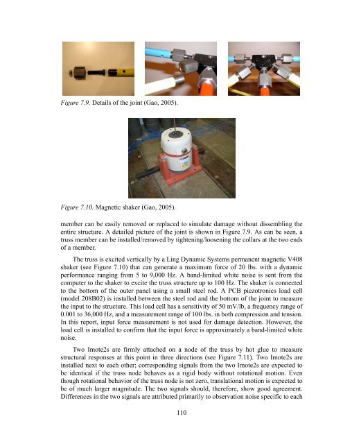
Figure 7.9. Details of the joint (Gao, 2005).<br />
Figure 7.10. Magnetic shaker (Gao, 2005).<br />
member can be easily removed or replaced to simulate damage without dissembling the<br />
entire structure. A detailed picture of the joint is shown in Figure 7.9. As can be seen, a<br />
truss member can be installed/removed by tightening/loosening the collars at the two ends<br />
of a member.<br />
The truss is excited vertically by a Ling Dynamic Systems permanent magnetic V408<br />
shaker (see Figure 7.10) that can generate a maximum force of 20 lbs. with a dynamic<br />
performance ranging from 5 to 9,000 Hz. A band-limited white noise is sent from the<br />
computer to the shaker to excite the truss structure up to 100 Hz. The shaker is connected<br />
to the bottom of the outer panel using a small steel rod. A PCB piezotronics load cell<br />
(model 208B02) is installed between the steel rod and the bottom of the joint to measure<br />
the input to the structure. This load cell has a sensitivity of 50 mV/lb, a frequency range of<br />
0.001 to 36,000 Hz, and a measurement range of 100 lbs. in both compression and tension.<br />
In this report, input force measurement is not used for damage detection. However, the<br />
load cell is installed to confirm that the input force is approximately a band-limited white<br />
noise.<br />
Two Imote2s are firmly attached on a node of the truss by hot glue to measure<br />
structural responses at this point in three directions (see Figure 7.11). Two Imote2s are<br />
installed next to each other; corresponding signals from the two Imote2s are expected to<br />
be identical if the truss node behaves as a rigid body without rotational motion. Even<br />
though rotational behavior of the truss node is not zero, translational motion is expected to<br />
be of much larger magnitude. The two signals should, therefore, show good agreement.<br />
Differences in the two signals are attributed primarily to observation noise specific to each<br />
110


