Structural Health Monitoring Using Smart Sensors - ideals ...
Structural Health Monitoring Using Smart Sensors - ideals ...
Structural Health Monitoring Using Smart Sensors - ideals ...
Create successful ePaper yourself
Turn your PDF publications into a flip-book with our unique Google optimized e-Paper software.
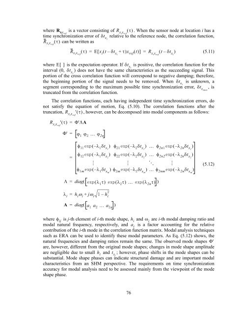
where R xxref<br />
is a vector consisting of R xi x ref<br />
. When the sensor node at location i has a<br />
time synchronization error of t xi<br />
relative to the reference node, the correlation function,<br />
<br />
can be written as<br />
R xi x ref<br />
R xi x ref<br />
= Ex i t – t xi<br />
+ x ref t = R xi x ref<br />
t – t xi<br />
<br />
(5.11)<br />
where E is the expectation operator. If t xi<br />
is positive, the correlation function for the<br />
interval (0, t xi<br />
) does not have the same characteristics as the succeeding signal. This<br />
portion of the cross correlation function will correspond to negative damping; therefore,<br />
the beginning portion of the signal needs to be removed. When t xi<br />
is unknown, a<br />
segment corresponding to the maximum possible time synchronization error, t xmax<br />
, is<br />
truncated from the correlation function.<br />
The correlation functions, each having independent time synchronization errors, do<br />
not satisfy the equation of motion, Eq. (5.10). The correlation functions after the<br />
truncation, R xi x ref<br />
' , however, can be decomposed into modal components as follows:<br />
R xi x ref<br />
' <br />
=<br />
'A<br />
'<br />
=<br />
2n<br />
=<br />
<br />
<br />
m<br />
– t x1<br />
–<br />
t x1<br />
2n –<br />
2n t x1<br />
<br />
–<br />
t x<br />
–<br />
t x<br />
2n2 –<br />
2n t x<br />
<br />
<br />
–<br />
<br />
t xm<br />
m<br />
–<br />
<br />
t xm<br />
2nm<br />
–<br />
2n<br />
t xm<br />
<br />
(5.12)<br />
= diag( <br />
<br />
<br />
<br />
2n<br />
<br />
)<br />
<br />
i<br />
= h i<br />
i<br />
+ j i<br />
– h i<br />
A = diag( a <br />
a <br />
a n<br />
)<br />
where ij<br />
is j-th element of i-th mode shape, h i<br />
and i<br />
are i-th modal damping ratio and<br />
modal natural frequency, respectively, and a i<br />
is a factor accounting for the relative<br />
contribution of the i-th mode in the correlation function matrix. Modal analysis techniques<br />
such as ERA can be used to identify these modal parameters. As Eq. (5.12) shows, the<br />
natural frequencies and damping ratios remain the same. The observed mode shapes '<br />
are, however, different from the original mode shapes; changes in mode shape amplitude<br />
are negligible due to small h i<br />
and t xi<br />
; however, phase shifts in the mode shapes can be<br />
substantial. Mode shape phases can indicate structural damage and are important modal<br />
characteristics from an SHM perspective. The requirements on time synchronization<br />
accuracy for modal analysis need to be assessed mainly from the viewpoint of the mode<br />
shape phase.<br />
76


