

Structural Health Monitoring Using Smart Sensors - ideals ...
Structural Health Monitoring Using Smart Sensors - ideals ...
Structural Health Monitoring Using Smart Sensors - ideals ...

Create successful ePaper yourself
Turn your PDF publications into a flip-book with our unique Google optimized e-Paper software.
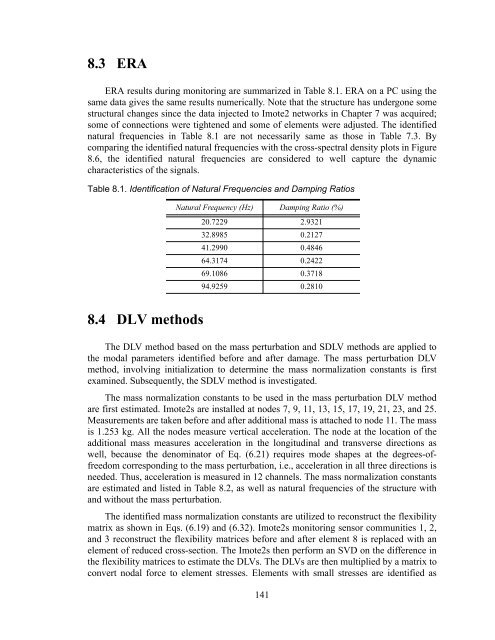
8.3 ERA<br />
ERA results during monitoring are summarized in Table 8.1. ERA on a PC using the<br />
same data gives the same results numerically. Note that the structure has undergone some<br />
structural changes since the data injected to Imote2 networks in Chapter 7 was acquired;<br />
some of connections were tightened and some of elements were adjusted. The identified<br />
natural frequencies in Table 8.1 are not necessarily same as those in Table 7.3. By<br />
comparing the identified natural frequencies with the cross-spectral density plots in Figure<br />
8.6, the identified natural frequencies are considered to well capture the dynamic<br />
characteristics of the signals.<br />
Table 8.1. Identification of Natural Frequencies and Damping Ratios<br />
Natural Frequency (Hz) Damping Ratio (%)<br />
20.7229 2.9321<br />
32.8985 0.2127<br />
41.2990 0.4846<br />
64.3174 0.2422<br />
69.1086 0.3718<br />
94.9259 0.2810<br />
8.4 DLV methods<br />
The DLV method based on the mass perturbation and SDLV methods are applied to<br />
the modal parameters identified before and after damage. The mass perturbation DLV<br />
method, involving initialization to determine the mass normalization constants is first<br />
examined. Subsequently, the SDLV method is investigated.<br />
The mass normalization constants to be used in the mass perturbation DLV method<br />
are first estimated. Imote2s are installed at nodes 7, 9, 11, 13, 15, 17, 19, 21, 23, and 25.<br />
Measurements are taken before and after additional mass is attached to node 11. The mass<br />
is 1.253 kg. All the nodes measure vertical acceleration. The node at the location of the<br />
additional mass measures acceleration in the longitudinal and transverse directions as<br />
well, because the denominator of Eq. (6.21) requires mode shapes at the degrees-offreedom<br />
corresponding to the mass perturbation, i.e., acceleration in all three directions is<br />
needed. Thus, acceleration is measured in 12 channels. The mass normalization constants<br />
are estimated and listed in Table 8.2, as well as natural frequencies of the structure with<br />
and without the mass perturbation.<br />
The identified mass normalization constants are utilized to reconstruct the flexibility<br />
matrix as shown in Eqs. (6.19) and (6.32). Imote2s monitoring sensor communities 1, 2,<br />
and 3 reconstruct the flexibility matrices before and after element 8 is replaced with an<br />
element of reduced cross-section. The Imote2s then perform an SVD on the difference in<br />
the flexibility matrices to estimate the DLVs. The DLVs are then multiplied by a matrix to<br />
convert nodal force to element stresses. Elements with small stresses are identified as<br />
141


