

Structural Health Monitoring Using Smart Sensors - ideals ...
Structural Health Monitoring Using Smart Sensors - ideals ...
Structural Health Monitoring Using Smart Sensors - ideals ...

You also want an ePaper? Increase the reach of your titles
YUMPU automatically turns print PDFs into web optimized ePapers that Google loves.
8000<br />
6000<br />
4000<br />
Drift (sec)<br />
2000<br />
0<br />
-2000<br />
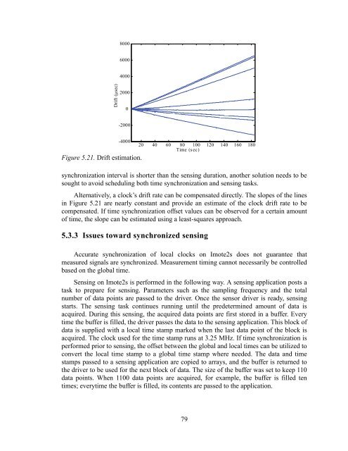
Figure 5.21. Drift estimation.<br />
-4000<br />
20 40 60 80 100 120 140 160 180<br />
Time (sec)<br />
synchronization interval is shorter than the sensing duration, another solution needs to be<br />
sought to avoid scheduling both time synchronization and sensing tasks.<br />
Alternatively, a clock’s drift rate can be compensated directly. The slopes of the lines<br />
in Figure 5.21 are nearly constant and provide an estimate of the clock drift rate to be<br />
compensated. If time synchronization offset values can be observed for a certain amount<br />
of time, the slope can be estimated using a least-squares approach.<br />
5.3.3 Issues toward synchronized sensing<br />
Accurate synchronization of local clocks on Imote2s does not guarantee that<br />
measured signals are synchronized. Measurement timing cannot necessarily be controlled<br />
based on the global time.<br />
Sensing on Imote2s is performed in the following way. A sensing application posts a<br />
task to prepare for sensing. Parameters such as the sampling frequency and the total<br />
number of data points are passed to the driver. Once the sensor driver is ready, sensing<br />
starts. The sensing task continues running until the predetermined amount of data is<br />
acquired. During this sensing, the acquired data points are first stored in a buffer. Every<br />
time the buffer is filled, the driver passes the data to the sensing application. This block of<br />
data is supplied with a local time stamp marked when the last data point of the block is<br />
acquired. The clock used for the time stamp runs at 3.25 MHz. If time synchronization is<br />
performed prior to sensing, the offset between the global and local times can be utilized to<br />
convert the local time stamp to a global time stamp where needed. The data and time<br />
stamps passed to a sensing application are copied to arrays, and the buffer is returned to<br />
the driver to be used for the next block of data. The size of the buffer was set to keep 110<br />
data points. When 1100 data points are acquired, for example, the buffer is filled ten<br />
times; everytime the buffer is filled, its contents are passed to the application.<br />
79


