

Structural Health Monitoring Using Smart Sensors - ideals ...
Structural Health Monitoring Using Smart Sensors - ideals ...
Structural Health Monitoring Using Smart Sensors - ideals ...

Create successful ePaper yourself
Turn your PDF publications into a flip-book with our unique Google optimized e-Paper software.
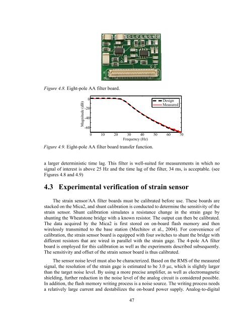
Figure 4.8. Eight-pole AA filter board.<br />
Magnitude (dB)<br />
0<br />
-20<br />
-40<br />
-60<br />
0 10 20 30 40 50 60 70<br />
Frequency (Hz)<br />
Figure 4.9. Eight-pole AA filter board transfer function.<br />
Design<br />
Measured<br />
a larger deterministic time lag. This filter is well-suited for measurements in which no<br />
signal of interest is above 25 Hz and the time lag of the filter, 34 ms, is acceptable. (see<br />
Figures 4.8 and 4.9)<br />
4.3 Experimental verification of strain sensor<br />
The strain sensor/AA filter boards must be calibrated before use. These boards are<br />
stacked on the Mica2, and shunt calibration is conducted to determine the sensitivity of the<br />
strain sensor. Shunt calibration simulates a resistance change in the strain gage by<br />
shunting the Wheatstone bridge with a known resistor. The output can then be calibrated.<br />
The data acquired by the Mica2 is first stored on on-board flash memory and then<br />
wirelessly transmitted to the base station (Mechitov et al., 2004). For convenience of<br />
calibration, the strain sensor board is equipped with four switches to shunt the bridge with<br />
different resistors that are wired in parallel with the strain gage. The 4-pole AA filter<br />
board is employed for this calibration as well as the experiments described subsequently.<br />
The sensitivity and offset of the strain sensor board is thus calibrated.<br />
The sensor noise level must also be characterized. Based on the RMS of the measured<br />
signal, the resolution of the strain gage is estimated to be 3.0 , which is slightly larger<br />
than the target noise level. By using a more precise amplifier, as well as electromagnetic<br />
shielding, further reduction in the noise level of the analog circuit is considered possible.<br />
In addition, the flash memory writing process is a noise source. The writing process needs<br />
a relatively large current and destabilizes the on-board power supply. Analog-to-digital<br />
47


