

Structural Health Monitoring Using Smart Sensors - ideals ...
Structural Health Monitoring Using Smart Sensors - ideals ...
Structural Health Monitoring Using Smart Sensors - ideals ...

Create successful ePaper yourself
Turn your PDF publications into a flip-book with our unique Google optimized e-Paper software.
EXPERIMENTAL VERIFICATION<br />
Chapter 8<br />
This chapter provides experimental verification of the SHM framework developed in<br />
this research. The SHM framework employing the DCS for SHM was realized on<br />
networks of Imote2s in Chapter 7. Numerical operations of the SHM system were<br />
numerically examined in a component-by-component manner by injecting acceleration<br />
response data to the network of Imote2s and processing the data. The system has been<br />
shown to be capable of processing acceleration data and localizing damage.<br />
The experimental verification of the proposed SHM framework uses acceleration<br />
response data measured by networks of Imote2s. Acceleration measurements and the<br />
subsequent data processing are performed before and after an element of the truss is<br />
replaced with a thinner element having a 52.7 percent cross-section reduction. The<br />
replaced element is detected by cluster head Imote2s. The experiment is repeated multiple<br />
times to assess reproducibility. Also, the experiment is repeated by replacing a different<br />
structural element to see the damage detection capability of the system in various<br />
elements. In this way, the ability of the proposed framework to localize damage is<br />
experimentally verified (Spencer & Nagayama, 2006).<br />
8.1 Experimental setup<br />
The SHM framework is experimentally verified on networks of Imote2s using the<br />
5.6m-long, three-dimensional truss structure discussed in Chapter 7. The truss and the<br />
structural node IDs and element IDs are shown again in Figures 8.1 and 8.2. The shaker is<br />
attached at node 17 and excites the truss with a band-limited white noise.<br />
The Imote2s are installed on the truss using plastic fixtures (see Figure 8.3). The<br />
fixture has two walls, each of which has two threaded holes. A set-screw is inserted into<br />
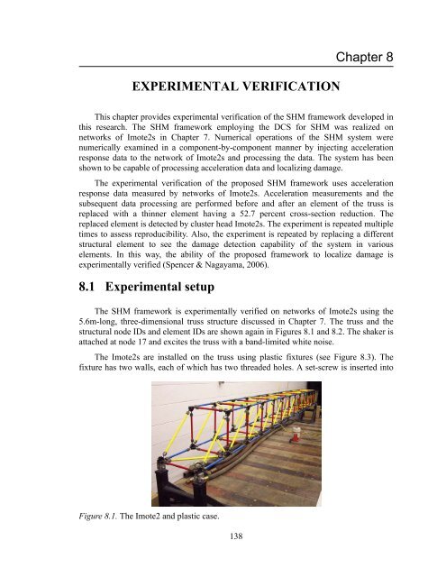
Figure 8.1. The Imote2 and plastic case.<br />
138


