

Structural Health Monitoring Using Smart Sensors - ideals ...
Structural Health Monitoring Using Smart Sensors - ideals ...
Structural Health Monitoring Using Smart Sensors - ideals ...

Create successful ePaper yourself
Turn your PDF publications into a flip-book with our unique Google optimized e-Paper software.
1<br />
Correlation Coefficient<br />
0<br />
-1<br />
-4.8 -4.7 -4.6 -4.5 -4.4<br />
Time Shift (sec)<br />
Figure 7.14. Correlation coefficients plotted against time shift.<br />
keeping the stopband cutoff frequency lower than the Nyquist frequency and completely<br />
eliminating the aliasing components, the cutoff frequency is set so that the aliasing<br />
components are above 100 Hz. For example, when sampling frequency is converted from<br />
560 to 280 Hz with the passband cutoff frequency of 100 Hz, the stopband cutoff<br />
frequency is set to 180 Hz instead of 140 Hz. Note that the actual sampling frequency of<br />
the sensor board may have 10 percent variation and is not exactly 560 Hz. The stopband<br />
cutoff frequency normalized to the upsampled sampling rate is set to be smaller than 180/<br />
560L, allowing the variation in the denominator. L is the upsampling factor. Likewise, the<br />
normalized passband cutoff frequency is set to be larger than 100/560L. In this way, a<br />
filter allowing aliased components outside of the frequency range of interest is designed<br />
with fewer filter coefficients than a filter completely eliminating aliased components.<br />
The length of the measured data is subject to the RAM size limitation. The sensing<br />
function on the Imote2 first stores data in the on-board RAM; the size of RAM limits the<br />
sensing duration. For example, a three-axis acceleration measurement using a 16-bit data<br />
type for each axis and having 11,264 data points occupies about 67 kB of RAM. Because<br />
sensing is first performed at a higher sampling frequency and then downsampled, the<br />
RAM originally occupied by the measured acceleration data is about 134 kB. 256 kB of<br />
RAM on the Imote2 does not allow continuous measurement of acceleration for an<br />
indefinite amount of time. Once the memory space becomes full, sensing is stopped, the<br />
stored data is copied to Flash memory, and sensing can be started again.<br />
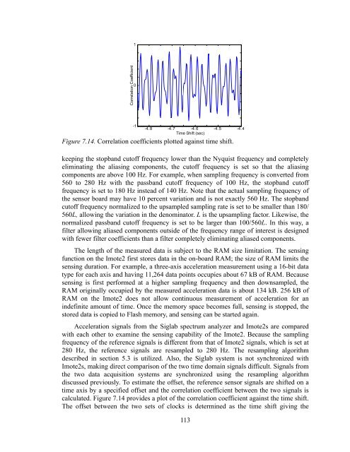
Acceleration signals from the Siglab spectrum analyzer and Imote2s are compared<br />
with each other to examine the sensing capability of the Imote2. Because the sampling<br />
frequency of the reference signals is different from that of Imote2 signals, which is set at<br />
280 Hz, the reference signals are resampled to 280 Hz. The resampling algorithm<br />
described in section 5.3 is utilized. Also, the Siglab system is not synchronized with<br />
Imote2s, making direct comparison of the two time domain signals difficult. Signals from<br />
the two data acquisition systems are synchronized using the resampling algorithm<br />
discussed previously. To estimate the offset, the reference sensor signals are shifted on a<br />
time axis by a specified offset and the correlation coefficient between the two signals is<br />
calculated. Figure 7.14 provides a plot of the correlation coefficient against the time shift.<br />
The offset between the two sets of clocks is determined as the time shift giving the<br />
113


