

Structural Health Monitoring Using Smart Sensors - ideals ...
Structural Health Monitoring Using Smart Sensors - ideals ...
Structural Health Monitoring Using Smart Sensors - ideals ...

Create successful ePaper yourself
Turn your PDF publications into a flip-book with our unique Google optimized e-Paper software.
Correlation function (g 2 )<br />
8 x10⁻³ Imote2<br />
Matlab<br />
4<br />
0<br />
-4<br />
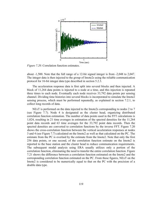
Figure 7.20. Correlation function estimates.<br />
0 1 2<br />
Time (sec)<br />
about -1,500. Note that the full range of a 12-bit signed integer is from -2,048 to 2,047.<br />
The integer data is then injected to the group of Imote2s using the reliable communication<br />
protocol for 16-bit integer data type described in section 5.2.3.<br />
The acceleration response data is first split into several blocks and then injected. A<br />
block of 11,264 data points is injected to a node at a time, and this injection is repeated<br />
three times to each node. Eventually each node receives 33,792 data points per sensing<br />
channel. Dividing time histories into several blocks is incorporated to simulate the Imote2<br />
sensing process, which must be performed repeatedly, as explained in section 7.2.1, to<br />
collect long records of data.<br />
NExT is performed on the data injected to the Imote2s corresponding to nodes 2 to 7<br />
(see Figure 7.7). Node 4 is designated as the cluster head, organizing distributed<br />
correlation function estimation. The number of data points used in the FFT calculations is<br />
1,024, resulting in 21 time averages in estimation of the spectral densities for the 11,264<br />
point data records and 63 time averages for the 33,792 point data records. Then the<br />
spectral densities are converted to correlation functions by the inverse FFT. Figure 7.20<br />
shows the cross-correlation function between the vertical acceleration responses at nodes<br />
3 and 4 (see Figure 7.7) calculated on the Imote2 as well as that calculated on the PC. The<br />
estimate from the PC is overlaid by the estimate from the Imote2. Note that only the first<br />
256 data points, or one second, of the correlation function estimate on the Imote2 is<br />
reported to the base station and the cluster head to reduce communication requirements.<br />
The subsequent modal analysis using ERA usually utilizes only a portion of the<br />
correlation function, eliminating the need to transfer the entire correlation function. Figure<br />
7.21 shows the difference between a correlation function estimated on the Imote2 and the<br />
corresponding correlation function estimated on the PC. From these figures, NExT on the<br />
Imote2 is considered to be numerically equal to that on the PC with the precision of a<br />
double data type.<br />
119


