

Structural Health Monitoring Using Smart Sensors - ideals ...
Structural Health Monitoring Using Smart Sensors - ideals ...
Structural Health Monitoring Using Smart Sensors - ideals ...

Create successful ePaper yourself
Turn your PDF publications into a flip-book with our unique Google optimized e-Paper software.
1<br />
2 Node ID 102 RETAKE 1<br />
3<br />
4 INCONSISTENT<br />
5<br />
6 Inconsistent Element ID: 8<br />
7<br />
8 ID 102 # of Damaged Element: 0<br />
9<br />
10<br />
11 Node ID 91 RETAKE 1<br />
12<br />
13 INCONSISTENT<br />
14<br />
15 Inconsistent Element ID: 8<br />
16<br />
17 ID 91 # of Damaged Element: 1<br />
18<br />
19 Damaged Element ID: 8<br />
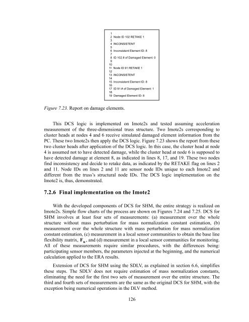
Figure 7.23. Report on damage elements.<br />
This DCS logic is implemented on Imote2s and tested assuming acceleration<br />
measurement of the three-dimensional truss structure. Two Imote2s corresponding to<br />
cluster heads at nodes 4 and 6 receive simulated damaged element information from the<br />
PC. These two Imote2s then apply the DCS logic. Figure 7.23 shows the report from these<br />
two cluster heads after application of the DCS logic. In this case, the cluster head at node<br />
4 is assumed not to have detected damage, while the cluster head at node 6 is supposed to<br />
have detected damage at element 8, as indicated in lines 8, 17, and 19. These two nodes<br />
find inconsistency and decide to retake data, as indicated by the RETAKE flag on lines 2<br />
and 11. Node IDs on lines 2 and 11 are sensor node IDs unique to each Imote2 and<br />
different from the truss’s structural node IDs. The DCS logic implementation on the<br />
Imote2 is, thus, demonstrated.<br />
7.2.6 Final implementation on the Imote2<br />
With the developed components of DCS for SHM, the entire strategy is realized on<br />
Imote2s. Simple flow charts of the process are shown on Figures 7.24 and 7.25. DCS for<br />
SHM involves at least four sets of measurements: (a) measurement over the whole<br />
structure without mass perturbation for mass normalization constant estimation, (b)<br />
measurement over the whole structure with mass perturbation for mass normalization<br />
constant estimation, (c) measurement in a local sensor communities to obtain the base line<br />
flexibility matrix, F u<br />
, and (d) measurement in a local sensor communities for monitoring.<br />
All of these measurements require similar procedures, with the differences being:<br />
participating sensor members, the parameters injected at the beginning, and the numerical<br />
calculation applied to the ERA results.<br />
Extension of DCS for SHM using the SDLV, as explained in section 6.6, simplifies<br />
these steps. The SDLV does not require estimation of mass normalization constants,<br />
eliminating the need for the first two sets of measurement over the entire structure. The<br />
third and fourth sets of measurements are the same as the original DCS for SHM, with the<br />
exception being numerical operations in the DLV method.<br />
126


