

Structural Health Monitoring Using Smart Sensors - ideals ...
Structural Health Monitoring Using Smart Sensors - ideals ...
Structural Health Monitoring Using Smart Sensors - ideals ...

Create successful ePaper yourself
Turn your PDF publications into a flip-book with our unique Google optimized e-Paper software.
1<br />
Normalized accumulated stress<br />
0.8<br />
0.6<br />
0.4<br />
0.2<br />
0<br />
3 4 5 6 7 8 9 1011 7 8 9 10 111213 1415 1112 1314 151617 1819<br />
Element ID<br />
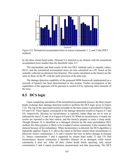
Figure 8.8. Normalized accumulated stress in sensor community 1, 2, and 3 (the SDLV<br />
method).<br />
by the three cluster head nodes. Element 8 is detected as an element with the normalized<br />
accumulated stress smaller than the threshold value, 0.3.<br />
The intermediate and final results of the two DLV methods such as singular values,<br />
DLVs, and the normalized accumulated stress are also calculated on a PC based on the<br />
centrally collected acceleration time histories. The results calculated on the Imote2 are the<br />
same as those on the PC with the same precision of the data type.<br />
The damage detection capability of the proposed SHM framework implemented on a<br />
network of Imote2s has been demonstrated in this section. Further investigation of the<br />
capabilities of the approach will be pursued in section 8.8 by replacing other elements of<br />
the truss.<br />
8.5 DCS logic<br />
Upon completing calculation of the normalized accumulated stresses, the three cluster<br />
heads exchange their damage detection results to perform the DCS logic given in Figure<br />
7.22. The log of the associated session recorded on the base station is presented in Figures<br />
8.9 and 8.10. These figures correspond to the damage detection results in Figures 8.7 and<br />
8.8, respectively. Because no inconsistency is reported, retake flags are set to zero as<br />
indicated by lines2, 9, and 16 in Figures 8.9 and 8.10. When no inconsistency is found, the<br />
results are reported to the base station, and the Imote2s prepare to enter a sleep mode.<br />
Though element 18 is identified as a damaged element by the mass perturbation DLV<br />
method, this false-positive is likely to be avoided if sensor community 4 also monitors this<br />
element because of the redundancy. When inconsistency is detected, the DCS algorithm is<br />
repeatedly applied. Figure 8.11 shows the report to the base station when inconsistency is<br />
observed. Sensor communities 3, 4, and 5 monitor the truss to detect damage at element<br />
21. Sensor communities 3 and 4 organized by cluster head nodes 73 and 135 find<br />
inconsistency. Sensor community 3 identifies element 16 as damaged, while sensor<br />
community 4 does not. After all three cluster heads finish reporting, only sensor<br />
communities 3 and 4 repeat acceleration measurement and data processing. The DCS<br />
143


