SwitchBlade x3112 Installation Guide - Allied Telesis
SwitchBlade x3112 Installation Guide - Allied Telesis
SwitchBlade x3112 Installation Guide - Allied Telesis

You also want an ePaper? Increase the reach of your titles
YUMPU automatically turns print PDFs into web optimized ePapers that Google loves.
Chapter 2: <strong>Installation</strong><br />
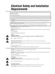
2. Identify the lowest 1/2” screw hole pattern on the rack mounting rails<br />
within the space reserved for the AT-SB<strong>x3112</strong> Chassis. Install one<br />
rack mount screw in each vertical rail - at the same height in the top<br />
screw hole of the lowest 1/2” hole pattern as displayed in Figure 28.<br />
The screws are used to support the chassis while you secure it to the<br />
rack.<br />
Screw<br />
Head<br />
6.4 mm (.25 in) away from rack<br />
Top screw hole of the lowest 1/2” hole pattern<br />
1791<br />
Figure 28. Rack Mounting Hole Locations<br />
Do NOT fully tighten these two screws at this time. The screw heads<br />
should protrude from the rack approximately 6.4 mm (.25 in).<br />
Unpacking the<br />
AT-SB<strong>x3112</strong><br />
Chassis<br />
To unpack the AT-SB<strong>x3112</strong> Chassis, perform the following procedure:<br />
1. Remove all components from the shipping package.<br />
2. Ensure that the following hardware components are included in your<br />
package. If any item is missing or damaged, contact your <strong>Allied</strong><br />
<strong>Telesis</strong> sales representative for assistance.<br />
– One AT-SB<strong>x3112</strong> Chassis (with pre-installed AT-<br />
SBx31FAN Tray and shipping brace)<br />
– Ten line card blank panels<br />
– Three power supply blank panels<br />
56


![AT-8100L/8POE-E [Rev B] - Allied Telesis](https://img.yumpu.com/25714603/1/190x245/at-8100l-8poe-e-rev-b-allied-telesis.jpg?quality=85)