SwitchBlade x3112 Installation Guide - Allied Telesis
SwitchBlade x3112 Installation Guide - Allied Telesis
SwitchBlade x3112 Installation Guide - Allied Telesis

You also want an ePaper? Increase the reach of your titles
YUMPU automatically turns print PDFs into web optimized ePapers that Google loves.
P<br />
O<br />
E<br />
0<br />
2<br />
4<br />
6<br />
8<br />
10<br />
P<br />
O<br />
E<br />
SBx31FAN<br />
POWER<br />
S<br />
Y<br />
S<br />
T<br />
E<br />
M<br />
AC<br />
DC<br />
FAULT<br />
S<br />
Y<br />
S<br />
T<br />
E<br />
M<br />
ESD<br />
SYSTEM<br />
POWER<br />
1<br />
3<br />
5<br />
7<br />
9<br />
11<br />
SBx3161<br />
<strong>SwitchBlade</strong> <strong>x3112</strong> <strong>Installation</strong> <strong>Guide</strong><br />
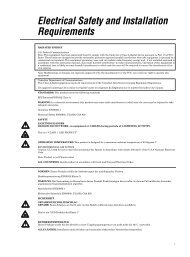
2. Remove the AT-SBx31FAN Tray from the chassis as shown in<br />
Figure 62.<br />
1811<br />
Figure 62. Removing the AT-SBx31FAN Tray from the Chassis<br />
3. Set the AT-SBx31FAN Tray aside for storage or shipment back to an<br />
<strong>Allied</strong> <strong>Telesis</strong> RMA (Return Materials Authorization) center. If you plan<br />
to return this unit to <strong>Allied</strong> <strong>Telesis</strong>, you must obtain an RMA number<br />
prior to shipment. Go to “Returning Products” on page 14 for<br />
information about how to obtain this number on the <strong>Allied</strong> <strong>Telesis</strong><br />
Technical Support web page.<br />
Installing a New<br />
AT-SBx31FAN<br />
Tray<br />
1. Remove the AT-SBx31FAN Tray from the shipping package.If this item<br />
is missing or damaged, contact your <strong>Allied</strong> <strong>Telesis</strong> sales<br />
representative for assistance.<br />
Note<br />
Store the packaging material in a safe location. You may use the<br />
original shipping material if you need to return the unit to <strong>Allied</strong><br />
<strong>Telesis</strong><br />
2. Insert the AT-SBx31FAN Tray into the vertical slot on the right side of<br />
the chassis into the slot as displayed in Figure 63 on page 86 until it is<br />
firmly seated against the front mounting rails of the chassis.<br />
85


![AT-8100L/8POE-E [Rev B] - Allied Telesis](https://img.yumpu.com/25714603/1/190x245/at-8100l-8poe-e-rev-b-allied-telesis.jpg?quality=85)