R308 AT Command Manual - wless.ru
R308 AT Command Manual - wless.ru
R308 AT Command Manual - wless.ru

Create successful ePaper yourself
Turn your PDF publications into a flip-book with our unique Google optimized e-Paper software.
<strong>R308</strong> <strong>AT</strong> <strong>Command</strong>s<br />
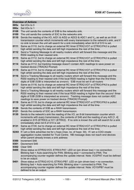
Overview of Actions<br />
005x Set I/Ox to 0<br />
006x Set I/Ox to 1<br />
0108 The unit sends the contents of S3B to the networks sink.<br />
0109 The unit sends the contents of S3C to the networks sink.<br />
0110 Sends the reading of the I/O, A/D1 & A/D2 or ADC0 & ADC1 and V cc as well as an 8-bit<br />
transmission counter which increments with every transmission to the network‟s sink, and if<br />
no sink is known the unit will search for a sink immediately when bit 8 of S10 is set.<br />
0111 Same as 0110, but to charge an external RC timer ETRX2:I/O7 or ETRX3:PA3 is pulled<br />
high whilst sending the data and left high impedance the rest of the time.<br />
0112 Send a Tracking Message to all nearby routers which will forward this message and the<br />
RSSI reading to their nearest sink.<br />
0113 Same as 0112, but to charge an external RC timer ETRX2:I/O7 or ETRX3:PA3 is pulled<br />
high whilst sending the data and left high impedance the rest of the time.<br />
0114 Same as 0112, but tracking message doesn‟t contain ADC readings to save power on<br />
tracked device (TRACK2 Prompt)<br />
0115 Same as 0114, but to charge an external RC timer ETRX2:I/O7 or ETRX3:PA3 is pulled<br />
high whilst sending the data and left high impedance the rest of the time.<br />
0116 Send a Tracking Message to all nearby routers which will forward this message and the<br />
RSSI reading to their nearest sink if the local RSSI reading is higher than the first three<br />
digits of S3B (S3B is interpreted as snnsnn). S3B must be set in all routers<br />
0117 Same as 0116, but to charge an external RC timer ETRX2:I/O7 or ETRX3:PA3 is pulled<br />
high whilst sending the data and left high impedance the rest of the time.<br />
0118 Send a Tracking Message to all nearby routers which will forward this message and the<br />
RSSI reading to their nearest sink if the local RSSI reading is higher than the second three<br />
digits of S3B (S3B is interpreted as snnsnn). Tracking message does not contain ADC<br />
readings to save power on tracked device (TRACK2 Prompt)<br />
0119 Same as 0118, but to charge an external RC timer ETRX2:I/O7 or ETRX3:PA3 is pulled<br />
high whilst sending the data and left high impedance the rest of the time.<br />
0120 Sends the contents of S3B as a RAW transmission.<br />
0121 Sends the contents of S3C as a RAW transmission.<br />
0130 Sends to the network‟s sink the reading of the I/O, an 8-bit transmission counter which<br />
increments with every transmission, the contents of S46 and the reading of any A/D [1..4]<br />
enabled in S15 (ETRX3) or S11 (ETRX2). If no sink is known the unit will search for a sink<br />
immediately when bit 8 of S10 is set<br />
0131 Same as 0130, but to charge an external RC timer ETRX2:I/O7 or ETRX3:PA3 is pulled<br />
high whilst sending the data and left high impedance the rest of the time.<br />
02XX If I am a Sink advertise me for x hops (max. no. of hops: 30). If I am a COO create<br />
aggregation routes needed for T<strong>ru</strong>st Centre. NB message does not reach end devices<br />
when parent already knows a sink address<br />
0300 Increment S46<br />
0301 Decrement S46<br />
0302 Clear S46<br />
0400 Show status on ETRX2:I/O3, ETRX3:PA7. LED on (pin driven low) = no connection.<br />
Blinking fast = Auto-searching for PAN. Blinking slow = connected to PAN. The<br />
accompanying counter register defines the update interval. Note: I/O3/PA7 must be defined<br />
to be an output.<br />
0401 Show status on ETRX2:I/O10, ETRX3:PB7. LED on (pin driven low) = no connection.<br />
Blinking fast = Auto-searching for PAN. Blinking slow = connected to PAN. The<br />
accompanying counter register defines the update interval. Note: I/O10/PB7 must be<br />
defined to be an output.<br />
©2012 Telegesis (UK) Ltd - 100 - <strong>AT</strong> <strong>Command</strong> <strong>Manual</strong> (Rev 3.08)