- Page 1 and 2:
AWS 924-948OWNER’S MANUAL
- Page 3 and 4:
IntroductionIMPORTANT INFORMATIONTh
- Page 5 and 6:
IntroductionCaution!When installing
- Page 7 and 8:
IntroductionMANUAL INDEXØ switch 3
- Page 9 and 10:
IntroductionPPAD switch 3-6PAN swit
- Page 11 and 12:
IntroductionMANUAL CONTENTSImportan
- Page 14 and 15:
IntroductionSECTION 3: ANALOGUE OPE
- Page 16 and 17:
IntroductionThe Default Button 4-10
- Page 18 and 19:
IntroductionThe Projects Tab 5-5Cop
- Page 20 and 21:
IntroductionAPPENDICESSection Conte
- Page 22 and 23:
IntroductionKey Features• Combina
- Page 24:
AWS InstallationThis page is intent
- Page 27 and 28:
Pre InstallationINSTALLATIONPRE-INS
- Page 29 and 30:
Pre InstallationUnpacking the Conso
- Page 31 and 32:
Studio IntegrationSTUDIO INTEGRATIO
- Page 33 and 34:
DAW ConnectionDAW CONNECTIONThe AWS
- Page 35 and 36:
DAW Connection• Using an RJ45 cab
- Page 37 and 38:
DAW ConnectionDirect Network Connec
- Page 39 and 40:
DAW ConnectionSetting Your Workstat
- Page 41 and 42:
DAW ConnectionLogic Pro 9When Logic
- Page 43 and 44:
DAW ConnectionNetwork Troubleshooti
- Page 45 and 46:
DAW ConnectionAssigning the AWS IP
- Page 47 and 48:
AWS 924-948OWner’S MAnuAlSeCTIOn
- Page 49 and 50:
AWS 924 Tutorial2b - AWS 948 TuTOrI
- Page 51 and 52:
AWS 924 TutorialAWS 924 TuTOrIAlStu
- Page 53 and 54:
AWS 924 Tutorial924 ChAnnel STrIPIn
- Page 55 and 56:
AWS 924 TutorialCenTre SeCTIOnAdjus
- Page 57 and 58:
AWS 948 TutorialAWS 948 TuTOrIAlFOC
- Page 59 and 60:
AWS 948 TutorialChAnnel MOdeSWhen i
- Page 61 and 62:
AWS 948 TutorialAnalogue-style In-l
- Page 63:
AWS 948 TutorialAdditional return M
- Page 66 and 67:
AWS 948 Tutorialbus routingTo route
- Page 68 and 69:
AWS 948 TutorialThis page is intent
- Page 70 and 71:
Analogue OperationsThis page is int
- Page 72 and 73:
Analogue OperationsMix and Rec Bus
- Page 74:
Analogue OperationsThe TFT ScreenTh
- Page 78 and 79:
Analogue OperationsInput configurat
- Page 80 and 81:
Analogue OperationsInsert PointTo s
- Page 82 and 83:
Analogue OperationsDirect OutputBy
- Page 84 and 85:
Analogue OperationsScribble StripsC
- Page 86 and 87:
Analogue OperationsBus MeterPanelOs
- Page 88 and 89:
Analogue OperationsMonitoring1Turn
- Page 90 and 91:
Analogue OperationsMonitor InsertTh
- Page 92 and 93:
Analogue OperationsMonitor Level Di
- Page 94 and 95:
Analogue OperationsDynamics Operati
- Page 96 and 97:
Analogue OperationsFoldback Headpho
- Page 98 and 99:
Analogue OperationsCommunications S
- Page 100 and 101:
Analogue OperationsConsole Setup Me
- Page 102 and 103:
Analogue OperationsDAW setupDAW set
- Page 104 and 105:
DAW ControlThis page is intentional
- Page 106 and 107:
DAW ControlMotion Control Panel 4-1
- Page 108 and 109:
DAW ControlThis page is intentional
- Page 110 and 111:
DAW ControlFocus ModesIn order to a
- Page 112 and 113:
DAW ControlCommunication with your
- Page 114 and 115:
DAW ControlSetup GuidelinesWhen mov
- Page 116 and 117:
DAW ControlThe Master Control Panel
- Page 118 and 119:
DAW ControlSHIFT allows selection o
- Page 120 and 121:
DAW ControlChannel Solo and Cut Til
- Page 122 and 123:
DAW Control5Select ModeAll 24 chann
- Page 124 and 125:
DAW ControlInput, Output and Send R
- Page 126 and 127:
DAW Control20Setting Pre and Post R
- Page 128 and 129:
DAW Control24Shuttle/Scrub WheelThe
- Page 130 and 131:
DAW ControlPlug-In Display ModesThe
- Page 132 and 133:
DAW ControlThis page is intentional
- Page 134 and 135:
DAW Control3. Edit Tools MenuEdit T
- Page 136 and 137:
DAW ControlThis page is intentional
- Page 138 and 139:
DAW ControlSuspending AutomationTo
- Page 140 and 141:
DAW ControlThe majority of DAW func
- Page 142 and 143:
DAW ControlThe Logic TemplateThe AW
- Page 144 and 145:
DAW ControlNuendo/Cubase TemplateAs
- Page 146 and 147:
DAW ControlNuendo Control screenFky
- Page 148 and 149:
DAW ControlSonar Console LayoutTRAC
- Page 150 and 151:
DAW ControlDigital Performer Templa
- Page 152 and 153:
DAW ControlThis page is intentional
- Page 154 and 155:
Projects and the RemoteThis page is
- Page 156 and 157:
Projects and the RemoteThis page is
- Page 158 and 159:
Projects and the RemoteThis page is
- Page 160 and 161:
Projects and the RemoteOnce a conne
- Page 162 and 163:
Projects and the RemoteCopying Titl
- Page 164 and 165:
Projects and the RemoteThis page is
- Page 166 and 167:
Projects and the RemoteThis page is
- Page 168 and 169:
Projects and the RemoteThis page is
- Page 170 and 171: Projects and the RemoteThis page is
- Page 172 and 173: Projects and the RemoteThis page is
- Page 174 and 175: Total RecallThis page is intentiona
- Page 176 and 177: Total RecallThis page is intentiona
- Page 178 and 179: Total RecallThis page is intentiona
- Page 180 and 181: Setup Guide: IO ConfigThis page is
- Page 182 and 183: Setup Guide: IO ConfigThe Channel D
- Page 184 and 185: Total RecallThis page is intentiona
- Page 186 and 187: Total RecallThis page is intentiona
- Page 188 and 189: Total RecallThis page is intentiona
- Page 190 and 191: AutomationThis page is intentionall
- Page 192 and 193: AutomationThis page is intentionall
- Page 194 and 195: Setup Guide: Console ConfigWORKING
- Page 196 and 197: AutomationOPERATIONActivating the A
- Page 198 and 199: AutomationTo start a mix, press Exe
- Page 200 and 201: AutomationJOIN AND REVISEAt any tim
- Page 202 and 203: AutomationSELECTING PROTECTIONEach
- Page 204 and 205: AutomationAUTOMATION OPTIONSTrimA m
- Page 206 and 207: AutomationSnap ModeSnap mode uses t
- Page 208 and 209: AutomationFADER LINKSFader Links ar
- Page 210 and 211: AutomationTo set up MMC locates, op
- Page 212 and 213: AutomationMIDI SYSEX LOADFor legacy
- Page 214 and 215: AppendicesThis page is intentionall
- Page 216 and 217: AppendicesThis page is intentionall
- Page 218 and 219: AppendicesConsole DimensionsSolid S
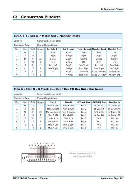
- Page 222 and 223: C: Connector PinoutsConnector Pinou
- Page 224 and 225: AppendicesThis page is intentionall
- Page 226 and 227: AppendicesThis page is intentionall
- Page 228 and 229: AppendicesThis page is intentionall
- Page 230 and 231: G: TroubleshootingAgain for the sak
- Page 232 and 233: G: TroubleshootingThe Channel Strip
- Page 234 and 235: G: TroubleshootingThe Channel Meter
- Page 236 and 237: G: TroubleshootingTroubleshooting C
- Page 238 and 239: AppendicesThis page is intentionall
- Page 240 and 241: AppendicesThis page is intentionall
- Page 242 and 243: J: Block DiagramsJ: BLOCK DIAGRAMSF